


L300P Inverter
Configuring Drive
Parameters
3–11
Analog Input
Settings
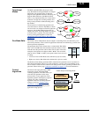
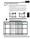
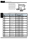
The inverter has the capability to accept external analog inputs that can command the output
frequency to the motor. Signals including voltage input (0 to +10V) at terminal [O], bipolar
input (-10 to +10V) at terminal [O2], and current input (4 to 20mA) at terminal [OI] are avail-
able. Terminal [L] serves as signal ground for the three analog inputs. The analog input settings
adjust the curve characteristics between the analog input and the frequency output.
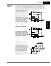
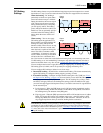
Adjusting [O–L] characteristics – In the
graph to the right, A013 and A014 select
the active portion of the input voltage
range. Parameters A011 and A012 select
the start and end frequency of the
converted output frequency range, respec-
tively. Together, these four parameters
define the major line segment as shown.
When the line does not begin at the origin
(A011 and A013 > 0), then A015 defines
whether the inverter outputs 0Hz or the
A011-specified frequency when the
analog input value is less than the A013
setting. When the input voltage is greater
than the A014 ending value, the inverter
outputs the ending frequency specified by
A012.
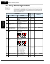
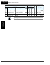
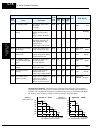
Adjusting [OI–L] characteristics – In
the graph to the right, A103 and A104
select the active portion of the input
current range. Parameters A101 and A102
select the start and end frequency of the
converted output frequency range, respec-
tively. Together, these four parameters
define the major line segment as shown.
When the line does not begin at the origin
(A101 and A103 > 0), then A105 defines
whether the inverter outputs 0Hz or the
A101-specified frequency when the
analog input value is less than the A103
setting. When the input voltage is greater
than the A104 ending value, the inverter
outputs the ending frequency specified by
A102.
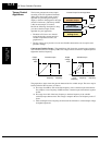
Adjusting [O2–L] characteristics – In
the graph to the right, A113 and A144
select the active portion of the input
voltage range. Parameters A111 and
A112 select the start and end frequency of
the converted output frequency range,
respectively. Together, these four parame-
ters define the major line segment as
shown. When the input voltage is less
than the A113 input starting value, the
inverter outputs the starting frequency
specified by A111. When the input
voltage is greater than the A114 ending
value, the inverter outputs the ending
frequency specified by A112.
% input
100%
10V
0%
0V
f
max. frequency
A013 A014
A012
A011
A015=0
A015=1
% input
100%
20mA
0%
4mA
A102
f
max. frequency
A101
A103 A104
A105=0
A105=1
% input
+100%
+10V
0
A112
f
max. fwd frequency
A111
A113
A114
–100%
-10V
f
max. rev frequency