


L300P Inverter
Operations
and Monitoring
4–9
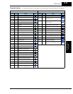
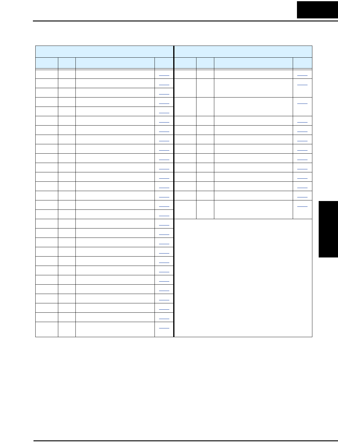
Terminal Listing Use the following table to locate pages for intelligent input and output material in this chapter.
Intelligent INPUTS Intelligent OUTPUTS
Symbol Code Name Page Symbol Code Name Page
RV 01 Reverse Run/Stop 4–11
RUN 00 Run signal 4–36
CF1 02 Multi-speed select, Bit 0 (LSB) 4–12 FA1 01 Freq. arrival type 1 –
constant speed
4–37
CF2 03 Multi-speed select, Bit 1 4–12
CF3 04 Multi-speed select, Bit 2 4–12 FA2 02 Freq. arrival type 2 –
over-frequency
4–37
CF4 05 Multi-speed select, Bit 3 (LSB) 4–12
JG 06 Jogging 4–15 OL 03 Overload advance notice signal 4–39
DB 07 External DC braking 4–16 OD 04 Output deviation for PID control 4–40
SET 08 Set (select) second motor data 4–17 AL 05 Alarm signal 4–41
2CH 09 2-stage accel and decel 4–18 FA3 06 Freq. arrival type 3 – at frequency 4–37
FRS 11 Free-run stop 4–19 IP 08 Instantaneous power failure signal 4–43
EXT 12 External trip 4–20 UV 09 Under-voltage signal 4–43
USP 13 Unattended start protection 4–21 RNT 11 Run time over 4–46
CS 14 Commercial power source 4–22 ONT 12 Power-ON time over 4–46
SFT 15 Software lock 4–24 THM 13 Thermal alarm signal 4–47
AT 16 Analog input voltage/current sel. 4–25 RMD 27 Run command source monitor
(–xFU2 and –xFE2 models only)
4–50
RS 18 Reset inverter 4–26
STA 20 Start (3-wire interface) 4–28
STP 21 Stop (3-wire interface) 4–28
F/R 22 FW, RV (3-wire interface) 4–28
PID 23 PID ON/OFF 4–29
PIDC 24 PID Reset 4–29
UP 27 Remote control Up func. 4–30
DWN 28 Remote control Down func. 4–30
UDC 29 Remote control data clearing 4–30
OPE 31 Operator control 4–31
SF1–7 32–38 Multi-speed bits 1 to 7 4–12
OLR 39 Overload restriction 4–32
ROK 49 Run enable for FW/RV
(–xFU2 and –xFE2 models only)
4–34