


L300P Inverter
Configuring Drive
Parameters
3–17
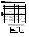
DC Braking
Settings
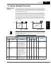
The DC braking feature can provide additional stopping torque when compared to a normal
deceleration to a stop. It can also ensure the motor and load are stopped before acceleration.
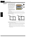
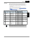
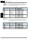
When decelerating – DC braking is
particularly useful at low speeds when
normal deceleration torque is minimal.
During deceleration, the inverter injects
a DC voltage into the motor windings
during deceleration below a frequency
you can specify (A052). The braking
power (A054) and duration (A055) can
both be set. You can optionally specify a
wait time before DC braking (A053),
during which the motor will free run
(coast).
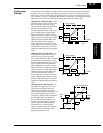
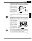
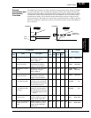
When starting – You can also apply
DC braking upon the application of a
Run command, specifying both the DC
braking force level (A057) and the
duration (A058). This will serve to stop
the rotation of the motor and the load,
when the load is capable of driving the
motor. This effect, sometimes called
“windmilling,” is common in fan appli-
cations. Often, air moving in duct work
will drive the fan in a backward direc-
tion. If an inverter is started into such a backward-rotating load, over-current trips can occur.
Use DC braking as an “anti-windmilling” technique to stop the motor and load, and allow a
normal acceleration from a stop. See also the “
Acceleration Pause Function” on page 3–20.
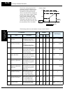
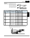
You can configure the inverter to apply DC braking at stopping only, at starting only, or both.
DC braking power (0–100%) can be set separately for stopping and starting cases.
You can configure DC braking to initiate in one of two ways:
1. Internal DC braking – Set A051=01 to enable internal braking. The inverter automatically
applies DC braking as configured (during stopping, starting, or both).
2. External DC braking – Configure an input terminal with option code 7 [DB] (see “
Exter-
nal Signal for DC Braking” on page 4–16 for more details). Leave A051=00, although this
setting is ignored when a [DB] input is configured. The DC braking force settings (A054
and A057) still apply. However, the braking time settings (A055 and A058) do not apply
(see level and edge triggered descriptions below). Use A056 to select level or edge detection
for the external input.
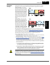
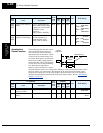
a. Level triggered – When the [DB] input signal is ON, the inverter immediately applies
DC injection braking, whether the inverter is in Run Mode or Stop Mode. You control
DC braking time by the duration of the [DB] pulse.
b. Edge triggered – When the [DB] input transitions OFF-to-ON and the inverter is in Run
Mode, it will apply DC braking only until the motor stops... then DC braking is OFF.
During Stop Mode, the inverter ignores OFF-to-ON transitions. Therefore, do not use
edge triggered operation when you need DC braking before acceleration.
CAUTION: Be careful to avoid specifying a braking time that is long enough to cause motor
overheating. If you use DC braking, we recommend using a motor with a built-in thermistor
and wiring it to the inverter’s thermistor input (see “
Thermistor Thermal Protection” on page 4–
27). Also refer to the motor manufacturer’s specifications for duty-cycle recommendations
during DC braking.
DC brakingFree runRunning
+
–
0
t
Output
voltage
A053 A055
A054
DC braking Running
+
–
0
t
Output
voltage
A058
A057