


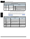
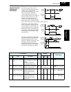
“C” Group: Intelligent Terminal Functions
Configuring Drive
Parameters
3–50
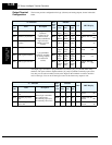
Note 1: To ensure safe inverter operation in networked applications, you cannot change an
intelligent terminal assignment to/from [RMD] (option code 27) via the network.
However, you can still read an [RMD] output assignment over the network.
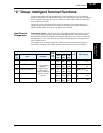
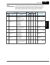
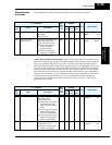
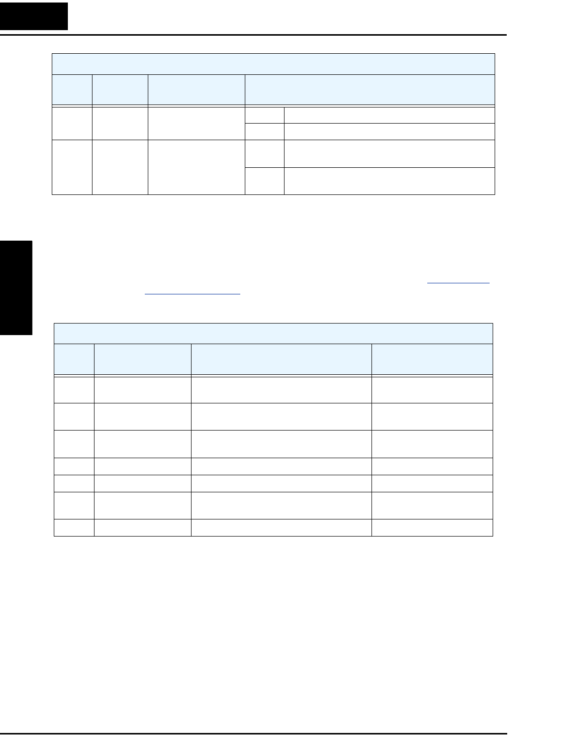
Analog Summary Table - The following table shows all seven functions available for assign-
ment to the three analog output terminals [FM], [AM], [AMI] at a glance. Detailed descrip-
tions, related parameters and settings, and example wiring diagrams are in “
Analog Output
Operation” on page 4–54.
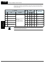
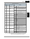
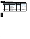
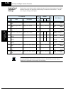
13 THM Thermal alarm signal ON when the thermal limit for the motor is exceeded
OFF when the thermal limit is not exceeded
27 RMD
*1
Run command source
monitor
(–xFU2 and –xFE2
models only)
ON when the Run command source is the operator keypad
(A002=02)
OFF when the Run command source is not the operator
keypad (A002=01, 03, 04, or 05)
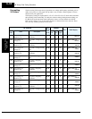
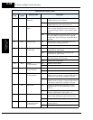
Output Function Summary Table
Option
Code
Terminal
Symbol
Function Name Description
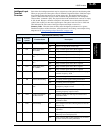
Analog Output Function Summary Table
Option
Code
Function Name Description
Corresponding Signal
Range
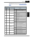
00 Output frequency Actual motor speed, represented by PWM
signal
0 to max. frequency in Hz
01 Output current Motor current (% of maximum rated output
current), represented by PWM signal
0 to 200%
03 Digital output
frequency
Output frequency (available only at FM
output)
0 to max. frequency in Hz
04 Output voltage Rated output voltage to motor 0 to 100%
05 Input power Rated input power 0 to 200%
06 Electronic thermal
overload
Percentage of electronic overload attained 0 to 100%
07 LAD frequency Internal ramp generator frequency 0 to max. frequency in Hz