


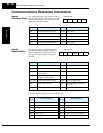
L300P Inverter
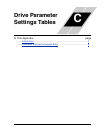
Appendix C
C–7
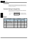
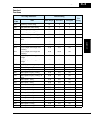
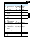
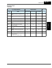
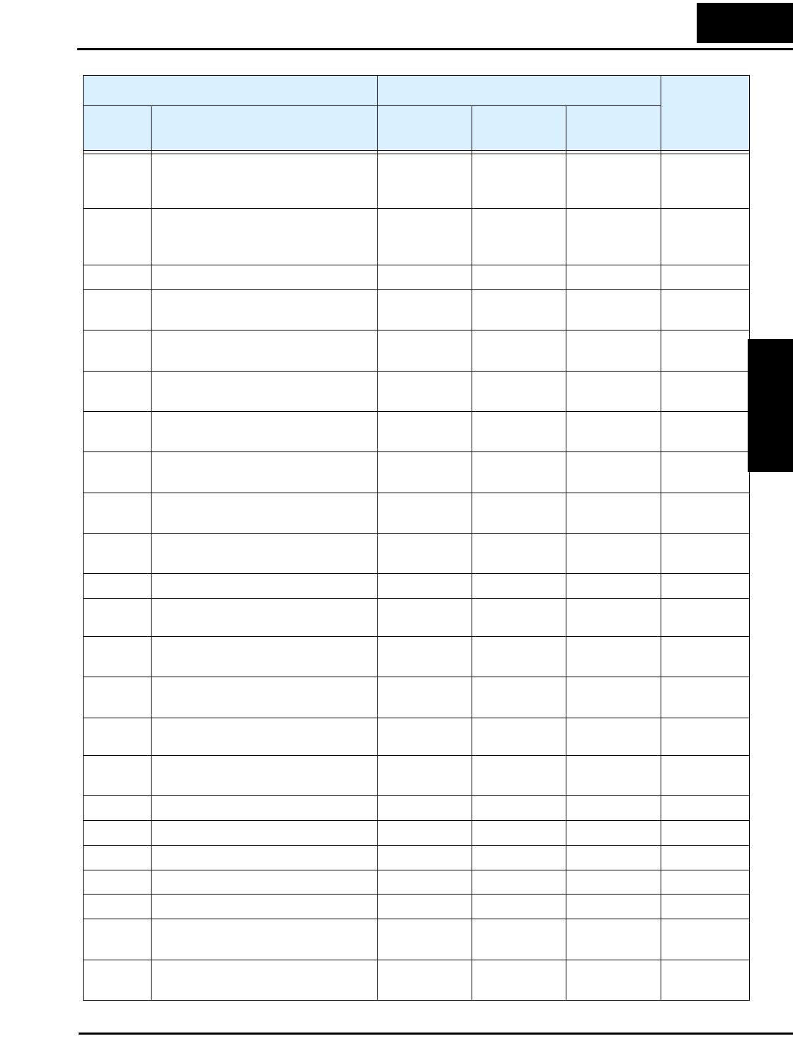
B012 Electronic thermal setting (calcu-
lated within the inverter from current
output)
Rated current
for each
inverter
Rated current
for each
inverter
Rated current
for each
inverter
B212 Electronic thermal setting (calcu-
lated within the inverter from current
output), 2nd motor
Rated current
for each
inverter
Rated current
for each
inverter
Rated current
for each
inverter
B013 Electronic thermal characteristic 01 00 00
B213 Electronic thermal characteristic,
2nd motor
01 00 00
B015 Free setting, electronic thermal
frequency (1)
0. 0. 0.
B016 Free setting, electronic thermal
current (1)
0.0 0.0 0.0
B017 Free setting, electronic thermal
frequency (2)
0. 0. 0.
B018 Free setting, electronic thermal
current (2)
0.0 0.0 0.0
B019 Free setting, electronic thermal
frequency (3)
0. 0. 0.
B020 Free setting, electronic thermal
current (3)
0.0 0.0 0.0
B021 Overload restriction operation mode 01 01 01
B022 Overload restriction setting
Rated current x
1.20
Rated current x
1.10
Rated current x
1.20
B023 Deceleration rate at overload restric-
tion
1.0 15.0 1.0
B024 Overload restriction operation mode
(2)
01 01 01
B025 Overload restriction setting (2)
Rated current x
1.20
Rated current x
1.20
Rated current x
1.20
B026 Deceleration rate at overload
restriction (2)
1.00 1.00 1.00
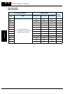
B031 Software lock mode selection 01 01 01
B034 Run/power-on warning time 0. 0. 0.
B035 Rotational direction restriction 00 00 00
B036 Reduced voltage start selection 06 06 06
B037 Function code display restriction 00 00 00
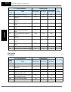
B080 [AM] terminal analog meter adjust-
ment
180 180 180
B081 [FM] terminal analog meter adjust-
ment
60 60 60
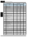
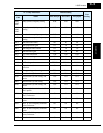
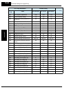
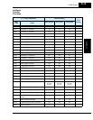
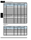
“B” Group Parameters Default Setting
User Setting
Func.
Code
Name
-FE2 (Europe) -FU2 (USA) -FR (Japan)