


L300P Inverter
Troubleshooting
and Maintenance
6–13
Capacitor
Replacement
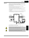
The capacitor bank consists of an assembly that slides out of the L300P unit. This means that
no soldering is required!
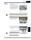
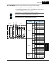
1. First, make sure that all power is removed
from the unit, and that you have waited 5
minutes before accessing the wiring area. Then
you’ll need to remove the metal wire entry
plate located at the bottom of the unit. This
may require you to disconnect all wires to the
power terminals. Then, just loosen the screws
as shown, and slide the wire entry plate
outward on its guides to remove.
WARNING: The screws that retain the capacitor bank assembly are part of the electrical
circuit of the high-voltage internal DC bus. Be sure that all power has been disconnected from
the inverter, and that you have waited at least 5 minutes before accessing the terminals or
screws. Be sure the charge lamp is extinguished. Otherwise, there is the danger of electrocution
to personnel.
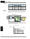
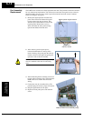
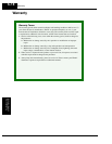
2. The capacitor bank assembly is locked into
the inverter via six screws that also make
several electrical connections. These six
screws are accessible just below the power
terminals as shown to the right.
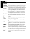
3. Grasp the capacitor bank assembly and gently
slide it out of the unit as shown to the right.
DO NOT try to force the removal; it will slide
out easily if all the screws in the steps above
have been removed.
4. Then slide in the new unit and replace all the
screws removed in steps 1) and 2).
CAUTION: Do not operate the inverter unless
you have replaced the six screws that connect the
capacitor bank assembly to the inverter’s
circuits. Otherwise, damage to the inverter may
occur.
Retention screws for wire entry plate
Retention screws locations for capacitor bank
Pull capacitor bank assembly outward
from L300P unit to remove