


L300P Inverter
Configuring Drive
Parameters
3–41
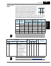
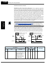
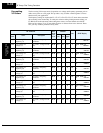
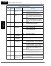
B090: Dynamic braking usage ratio – This parameter limits the amount of time the inverter
can use the dynamic braking accessory device without entering the Trip Mode. Please refer to
“
Dynamic Braking” on page 5–6 for more information on dynamic braking accessories.
NOTE: When cooling fan control is enabled (B092=01) the inverter always turns the fan ON
for 5 minutes immediately after powerup. This will cool the inverter in case the inverter / motor
is still warm from prior running before a short power outage.
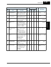
B090 Dynamic braking usage
ratio
Selects the braking duty
cycle for the dynamic
braking resistor (total brake
% ON-time per 100 sec.
interval).
Range is 0.0 to 100.0%
0%Dynamic braking
disabled
>0% Enabled, per value
✘ ✔ 00 00 00 —
>b090 BRD
%ED 000.0%
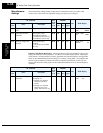
B091 Stop mode selection Selects how the inverter
normally stops the motor
(Run command or signal
goes OFF)
Two option codes:
00 DEC (decelerate and
stop)
01 FRS (free-run to stop)
✘ ✘ 00 00 00 —
>b091 RUN
STOP DEC
B092 Cooling fan control
(see note below)
Two option codes:
00 Fan always ON
01 Fan ON during RUN,
OFF during STOP
✘ ✘ 00 00 00 —
>b092 INITIAL
FAN-CTL OFF
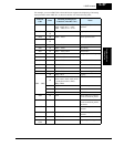
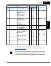
B095 Dynamic braking
control
Three option codes:
00 Disable
01 Enable during RUN only
02 Enable always
✘ ✔ 00 00 00 —
>b095 BRD
Mode OFF
B096 Dynamic braking
activation level
Range is:
330 to 380V (200V class),
660 to 760V (400V class)
✘ ✔ 360/
720
360/
720
360/
720
V
>b096 BRD
LEVEL 360Vdc
B098 Thermistor for thermal
protection control
Three option codes:
00 Disable
01 Enable-PTC thermistor
02 Enable-NTC thermistor
✘ ✔ 00 00 00 —
>b098 THERM
SELECT OFF
B099 Thermal protection level
setting
Thermistor resistance
threshold at which trip
occurs.
Range is 0.0 to 9999 Ohms
✘ ✔ 3000 3000 3000
Ohms >b099 THERM
LEVEL 3000ohm
“B” Function
Run
Mode
Edit
Lo Hi
Defaults
Units
SRW Display
Func.
Code
Name Description
–FE2
(CE)
–FU2
(UL)
–FR
(Jpn)