


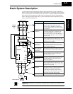

L300P Inverter
Inverter Mounting
and Installation
2–13
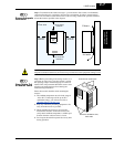
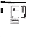
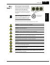
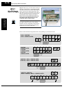
Step 5: The wiring enters the inverter through
the entry/exit plate as shown to the right. The
rubber grommets have a solid, thin membrane,
so that unused ones continue to seal the opening.
To create an opening, use a sharp knife and
carefully cut an “X” in the center of the
grommet as shown. Be especially careful to
avoid cutting into the thick outer ring, so that the
wiring will have a cushion from contacting the
metal plate.
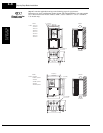
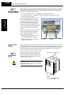
NOTE: Some inverter models will have a
wiring box for NEMA rating compliance. Make
sure the wire entry to the NEMA box also has
protective cushion from chaffing of insulation.
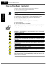
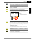
Before proceeding, please study the caution and warning messages below.
WARNING: “Use 60/75°C Cu wire only” or equivalent.
WARNING: “Open Type Equipment.”
WARNING: “A Class 2 circuit wired with Class 1 wire” or equivalent.
WARNING: “Suitable for use on a circuit capable of delivering not more than 10,000 rms
symmetrical amperes, 240 V maximum.” For models with suffix L.
WARNING: “Suitable for use on a circuit capable of delivering not more than 10,000 rms
symmetrical amperes, 480 V maximum.” For models with suffix H.
HIGH VOLTAGE: Be sure to ground the unit. Otherwise, there is a danger of electric shock
and/or fire.
HIGH VOLTAGE: Wiring work shall be carried out only by qualified personnel. Otherwise,
there is a danger of electric shock and/or fire.
HIGH VOLTAGE: Implement wiring after checking that the power supply is OFF. Otherwise,
you may incur electric shock and/or fire.
HIGH VOLTAGE: Do not connect wiring to an inverter or operate an inverter that is not
mounted according the instructions given in this manual. Otherwise, there is a danger of elec-
tric shock and/or injury to personnel.
5
Prepare for
Wiring
Cut grommet(s) for
use as shown