


L300P Inverter
Inverter Mounting
and Installation
2–23
Using the Front Panel Keypad
Front Panel
Introduction
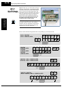
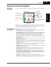
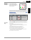
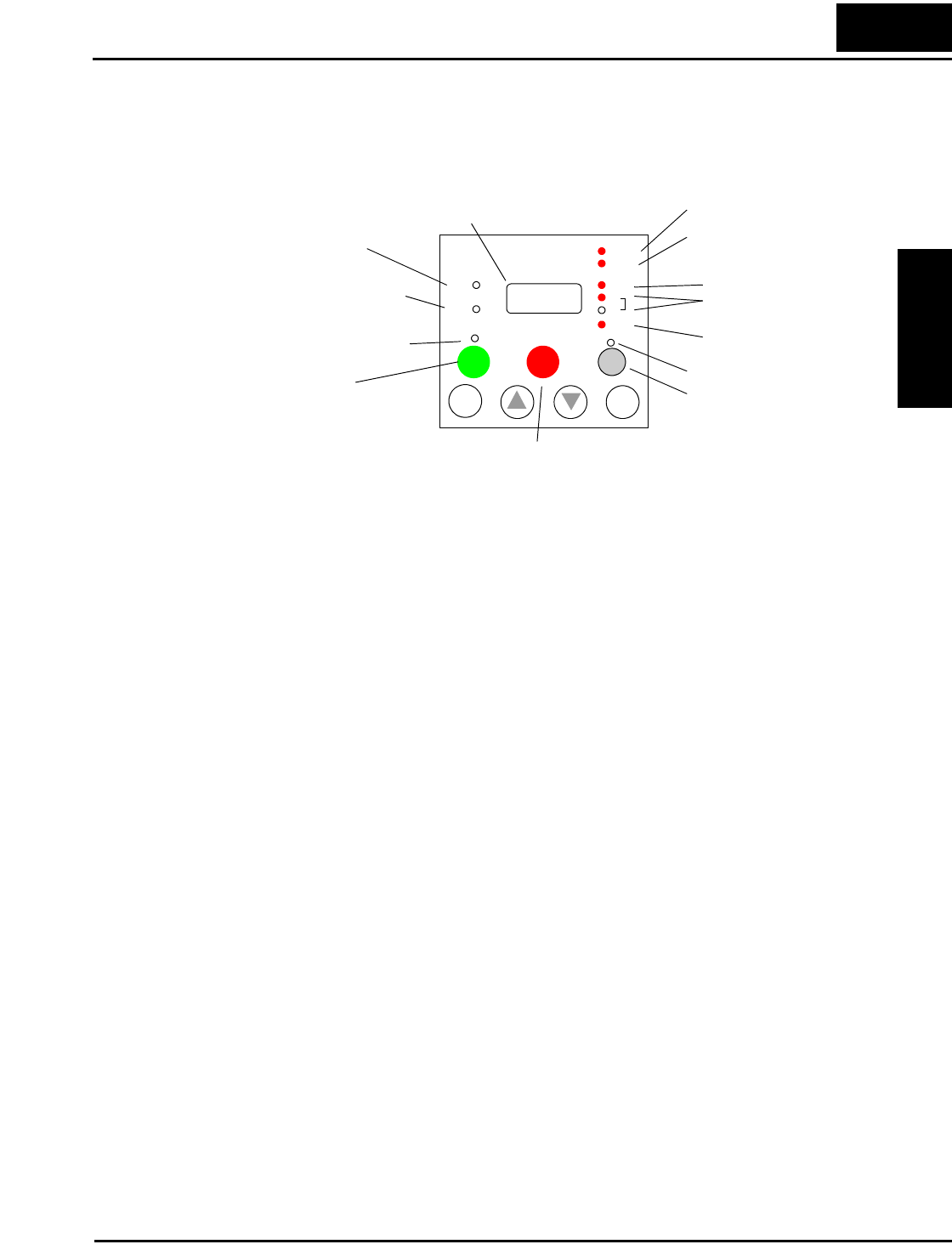
Please take a moment to familiarize yourself with the keypad layout shown in the figure below.
The display is used in programming the inverter’s parameters, as well as monitoring specific
parameter values during operation. Many functions are applicable only during the initial instal-
lation, while others are more useful for maintenance or monitoring.
Parameter Editing
and Controls
The front panel controls and indicators are described as follows:
• Run/Stop LED – ON when the inverter output is ON and the motor is developing torque,
and OFF when the inverter output is OFF (Stop Mode).
• Program/Monitor LED – This LED is ON when the inverter is ready for parameter editing
(Program Mode). It is normally OFF when the parameter display is monitoring data
(Monitor Mode). However, the PRG LED will be ON whenever you are monitoring the
value of parameter D001. (When the keypad is enabled as the frequency source via
A001=02, you can edit the inverter frequency directly from D001 monitor display by using
the Up/Down keys.)
• Run Key Enable LED – is ON when the inverter is ready to respond to the Run key, OFF
when the Run key is disabled.
• Run Key – Press this key to run the motor (the Run Enable LED must be ON first). Parame-
ter F004, Keypad Run Key Routing, determines whether the Run key generates a Run FWD
or Run REV command.
• Stop/Reset Key – Press this key to stop the motor when it is running (uses the programmed
deceleration rate). This key will also reset an alarm that has tripped.
• Potentiometer – allows an operator to directly set the motor speed when the potentiometer
is enabled for output frequency control.
• Potentiometer Enable LED – ON when the potentiometer is enabled for value entry.
• Parameter Display – a 4-digit, 7-segment display for parameters and function codes.
• Display Units: Hertz/Volts/Amperes/kW/% – These LEDs indicate the units associated
with the parameter display. When the display is monitoring a parameter, the appropriate
LED is ON. In the case of kW units, both Volts and Amperes LEDs will be ON. An easy way
to remember this is that kW = (V x A)/1000.
• Power LED – This LED is ON when the power input to the inverter is ON.
• Alarm LED – This LED is ON when an alarm condition has tripped the inverter. Clearing
the alarm will turn this LED OFF again. See Chapter 6 for details on clearing alarms.
Hz
POWER
A
RUN
PRG
RUN
STOP
RESET
MIN
MAX
HITACHI
FUNC
1
2
%
ALARM
STR
V
kW
Run/Stop LED
Program/Monitor LED
Run Key Enable LED
Run Key
Power LED
Alarm LED
Display Units LEDs
Hertz
Volts or Amperes
(kW = both ON)
Percent
Parameter Display
Potentiometer Enable LED
Potentiometer
Stop/Reset Key
50.0