


Intel
®
IXP43X Product Line of Network Processors
April 2007 HDG
Document Number: 316844; Revision: 001US 17
Hardware Design Guidelines—Intel
®
IXP43X Product Line of Network Processors
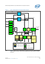
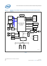
3.0 General Hardware Design Considerations
This chapter contains information for implementing and interfacing with major
hardware blocks of the Intel
®
IXP43X Product Line of Network Processors. Such blocks
include DDRII/I SDRAM, Flash, Ethernet PHYs, UART and other peripherals interfaces.
Signal definition tables list resistor recommendations for pull-ups and pull-downs.
Features disabled by a specific part number, do not require pull-ups or pull-downs.
Therefore, all pins can be left unconnected. Features enabled by a specific part number
and required to be Soft Fuse-disabled, only require pull-ups or pull-downs in the
clock-input signals. Other conditions can require pull-up or pull-down resistors for
configuration purposes at power on or reset. In the same way, open-drain outputs must
be pulled high.
Warning: With the exception of USB_V5REF all other I/O pins of the IXP43X network processors
are not 5.0-V tolerant.
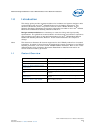
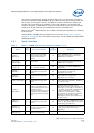
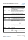
Table 2 gives the legend for interpreting the Type field used in the signal-definition
tables that are covered in this chapter.
3.1 Soft Fusible Features
Soft Fuse Enable/Disable is a method to enable or disable features in hardware,
virtually disconnecting the hardware modules from the processor.
Some of the features offered in the IXP43X product line of network processors can be
Soft Fuse Enabled/Disabled during boot. It is recommended that if a feature is not used
in the design, the feature be soft disabled. This helps reduce power and maintain the
part running at a cooler temperature. When Soft Fuse Disabled, a pull-up resistor must
be connected to each clock input pins of the disabled feature interface. All other signals
can be left unconnected.
Soft Fuse Enable/Disable can be done by writing to EXP_UNIT_FUSE_RESET register.
For more information refer to the Intel
®
IXP43X Product Line of Network Processors
Developer’s Manual and review the register description.
Table 2. Signal Type Definitions
Symbol Description
I Input pin only
O Output pin only
I/O Pin can be an input or output
OD Open-drain pin
TRI Tri-State pin
PWR Power pin
GND Ground pin
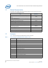
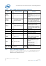
Table 3. Soft Fusible Features (Sheet 1 of 2)
Name Description
PCI The complete bus must be enabled or disable.
HSS0 Can only be disable as a pair.
UTOPIA
while enabling UTOPIA, MACs on NPE A is disabled.
while enabling MACs on NPE A, UTOPIA is disabled.