


Intel
®
IXP43X Product Line of Network Processors—Hardware Design Guidelines
Intel
®
IXP43X Product Line of Network Processors
HDG April 2007
22 Document Number: 316844; Revision: 001US
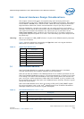
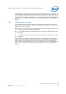
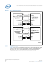
3.3.2 Reset Configuration Straps
At power up or whenever RESET_IN_N is asserted, the Expansion-bus address outputs
are switched to inputs and the state of the inputs are captured and stored in
Configuration Register 0, bits 23 through 0. This occurs when PLL_LOCKED is de-
asserted.
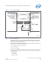
The strapping of Expansion-bus address pins can be done by placing external pull-down
resistors at the required address pin. It is not required to use external pull-up resistors,
by default upon reset all bits on Configuration Register 0 are set High, unless an
external pull down is used to set them Low. For example to register a bit low or high in
the Configuration Register 0, do the following:
Place an external 470Ω pull-down resistor to register a bit LOW in the Configuration
Register 0.
No external pull-up is required; upon reset, bits are set high by default.
The state of the boot-strapping resistor is registered on the first cycle after the
synchronous de-assertion of the reset signal. These bits can be read or written as
needed for desired configurations. It is recommended that only Bit 31, Memory Map, be
changed from 1 to 0 after execution of boot code from external flash.
Refer to the Intel
®
IXP43X Product Line of Network Processors Developer’s Manual for
a complete bit description of Configuration Register 0.
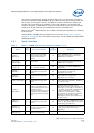
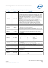
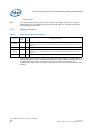
EX_CS_N[3:0] I/O Yes
Use series termination resistor, 10Ω to 33Ω at the source.
Use 10KΩ resistors pull-ups to ensure that the signal remains de-asserted.
EX_DATA[15:0] I/O No Expansion-bus, bidirectional data.
EX_IOWAIT_N I Yes Should be pulled high through a 10-KΩ resistor when not being utilized in the system.
Table 5. Expansion Bus Signal Recommendations (Sheet 2 of 2)
Name
Type
Field
Pull
Up
Down
Recommendations
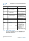
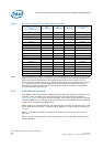
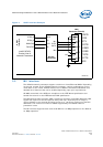
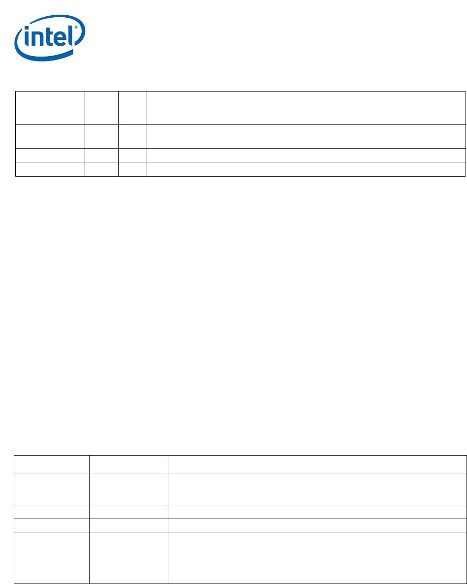
Table 6. Boot/Reset Strapping Configuration (Sheet 1 of 2)
Name Function Description
EX_ADDR[23:21]
Intel XScale
®
Processor
Clock Set[2:0]
Allow a slower Intel XScale
®
Processor clock speed to override device fuse settings.
But cannot be used to over clock core speed. Refer to Table 7 for additional
information.
EX_ADDR[20:17] Customer Customer-defined bits. (Might be used for board revision.)
EX_ADDR[16:12] (Reserved) (Reserved)
EX_ADDR[11] DDR_MODE
DDRI or DDRII mode selection:
0 - DDRII mode (400MHz)
1 - DDRI mode (266MHz)
DDR_mode or DDR clock speed selection bit is read only and strapped in from exp
address bit 11 upon activation of reset_early_n and reset_cold_n.