


Intel
®
IXP43X Product Line of Network Processors
April 2007 HDG
Document Number: 316844; Revision: 001US 67
Hardware Design Guidelines—Intel
®
IXP43X Product Line of Network Processors
6.0 PCI Interface Design Considerations
The IXP43X network processors have a single, 32-bit PCI device module that runs at 33
MHz. This chapter describes some basic guidelines to help design hardware that
interfaces with PCI devices.
The PCI module is compatible with the PCI Local Bus Specification, Rev. 2.2. For a
complete functional description and physical requirements, see the PCI Local Bus
Specification, Rev. 2.2.
6.1 Electrical Interface
The electrical definition is restricted to 3.3 V signaling environment. The device is not
5 V tolerant. All devices interfacing with the PCI module must operate at 3.3 V.
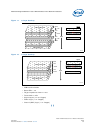
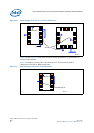
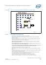
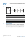
6.2 Topology
Interfacing devices must be connected in a daisy-chain topology. When more than one
device is in the bus, connecting stubs must be kept as short as possible.
There is a limitation to the number of devices connected to the internal arbiter. If more
than four devices are required to be connected, an external arbiter is required.
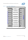
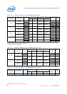
The system time budget must be satisfied for 33 MHz cycles. The following equation
and timing parameters must be met while routing a board that interfaces with a single
PCI device or up to four devices as shown in Figure 23.
T
CYC
≥ T
VAL
+T
PROP
+ T
SKEW
+ T
SU
where:
T
VAL
= Valid Output Delay
T
PROP
= Bus Propagation Delay (maximum time for complete flight)
T
SKEW
= Total Clock Skew
T
SU
= Input Setup Time
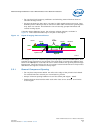
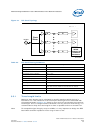
When defining the maximum length of segments A and B as shown in Figure 23, the
calculation must:
• Include an additional trace length segment from the PCI connector to the input
device within the expansion PCI card
• Assume the segment to be 1.5 inch
• Use trace propagation delay of 150 to 190 ps/in as specified by the PCI standard
@33 MHz T
CYC
= 30 nSec T
VAL
= 11 nSec T
PROP
= 10 nSec T
SKEW
= 2 nSec T
SU
= 7 nSec