


Intel
®
IXP43X Product Line of Network Processors
April 2007 HDG
Document Number: 316844; Revision: 001US 35
Hardware Design Guidelines—Intel
®
IXP43X Product Line of Network Processors
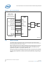
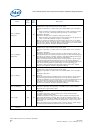
2. If a 1.5-KΩ, pull-up resistor is connected to USB_P_NEG line, the USB port is
identified as Low-speed mode.
To maintain signal integrity and minimize end-users termination mismatch, the IXP43X
network processors require external series termination resistors. The value of the
terminating resistors is based on the operational speed and length of the transmission
line.
Refer to following termination guidelines for High-speed:
1. High-speed USB designs require parallel termination at both the transmitter and
receiver. For host controller designs that use external termination resistors, place
the termination resistors as close as possible to the host controller signal pins.
Recommend less than 200 mils if possible. Follow the manufacturer’s
recommendation for the termination value needed to obtain the required 45 ohm to
ground parallel HS termination.
2. For downstream ports, a 15 kΩ pull down resistor on the connector side of the
termination is required for device connection detection purposes. Note that this pull
down might be integrated into the host controller silicon. Follow the manufacturer’s
recommendation for the specific part used.
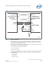
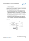
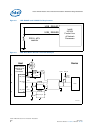
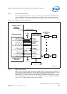
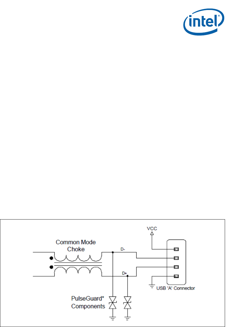
3. A common mode (CM) choke should be used to terminate the high speed USB bus
if they should pass EMI testing. Place the CM choke as close as possible to the
connector as shown in Figure 8 on page 36. Common mode chokes can provide
required noise attenuation. Design can include a common mode choke footprint to
provide a stuffing option in the event the choke is needed to pass EMI testing.
Note: Common mode chokes degrade signal quality, thus they should only be used if EMI is a
known problem.
Figure 7. Common Mode Choke