


Intel
®
IXP43X Product Line of Network Processors
April 2007 HDG
Document Number: 316844; Revision: 001US 65
Hardware Design Guidelines—Intel
®
IXP43X Product Line of Network Processors
— Space within a group can be just 1 w.
— Space between clock signals or clock to any other signal should be 3 w. The
coupled noise between adjacent traces decreases by the square of the distance
between the adjacent traces.
5.2.6 EMI Design Considerations
It is strongly recommended that good electromagnetic interference (EMI) design
practices must be followed while designing with the IXP43X network processors.
• Information on spread-spectrum clocking is available in the Intel
®
IXP4XX Product
Line of Network Processors and IXC1100 Control Plane Processor: Spread-
Spectrum Clocking to Reduce EMI Application Note.
• Place high-current devices as closely as possible to the power sources.
• Proper termination of signals can reduce reflections, which can emit a high-
frequency component that contribute to more EMI than the original signal itself.
• Ferrite beads can be used to add high frequency loss to a circuit without
introducing power loss at DC and low frequencies. They are effective when used to
absorb high-frequency oscillations from switching transients or parasitic
resonances within a circuit.
• Keep rise and fall times as slow as possible. Signals with fast rise and fall times
contain many high-frequency harmonics which can radiate significantly.
• A solid ground is essential at the I/O connector to chassis and ground plane.
• Keep the power plane shorter than the ground plane by at least 5x the spacing
between the power and ground planes.
• Stitch together all ground planes around the edge to the board every 100 to
200 mil. This helps reduce EMI radiating out of the board from inner layers.
5.2.7 Trace Impedance
All signal layers require controlled impedance of 50 Ω ±10 % microstrip or stripline
(unless otherwise specified) where appropriate. Selecting the appropriate board stack-
up to minimize impedance variations is very important.
When calculating flight times, it is important to consider the minimum and maximum
trace impedance based on the switching neighboring traces.
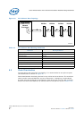
5.2.8 Power and Ground Plane
Power and ground planes should have sufficient decoupling capacitors to ensure
sustainable current needed for high-speed switching devices. See Section 3.14.1,
“Decoupling Capacitance Recommendations” on page 54.
• It is highly recommended to use sufficient internal power and ground planes.
•The Intel
®
IXP43X Product Line requires a number of power supplies. It is
appropriate to use power islands in the power plane under the processor, as it will
be too expensive to have a power plane for each power source.
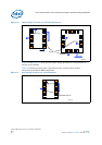
• Power islands must be large enough to include the required power supply
decoupling capacitance, and the necessary connection to the voltage source and
destination.
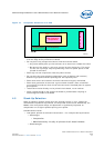
• Islands can be separated by a minimum of 20-mil air gap.
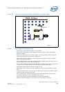
• Use at least one via per power or ground pin, wherever possible use more vias,
depending on current drawn.