


Intel
®
IXP43X Product Line of Network Processors
April 2007 HDG
Document Number: 316844; Revision: 001US 21
Hardware Design Guidelines—Intel
®
IXP43X Product Line of Network Processors
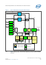
3.3 Expansion Bus
The Expansion Bus of the IXP43X network processors is specifically designed for
compatibility with Intel-and Motorola* style microprocessor interfaces.
The expansion bus controller includes a 24-bit address bus and a 16-bit wide data path,
running at a maximum speed of 80 MHz from an external clock oscillator. The bus can
be configure to support the following target devices:
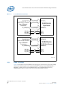
The expansion bus controller also has an arbiter that supports up to four external
devices that can master the expansion bus. External masters can be used to access
external slave devices that reside on the expansion bus, including access to internal
memory mapped regions within the IXP43X network processors.
All supported modes are seamless and no additional glue logic is required. Other cycle
types can be supported by configuring the Timing and Control Register for Chip Select.
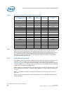
The expansion interface functions support 8-bit or 16-bit data operation and allows an
address range of 512 bytes to 16 MBs, using 24 address lines for each of the four
independent chip selects.
Access to the expansion-bus interface is completed in five phases. Each of the five
phases can be lengthened or shortened by setting various configuration registers on a
per-chip-select basis. This feature allows the IXP43X network processors to connect to
a wide variety of peripheral devices with varying speeds.The expansion interface
supports Intel or Motorola* microprocessor style bus cycles. The bus cycles can be
configured to be multiplexed address/data cycles or separate address/data cycles for
each of the four chip-selects.
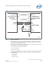
The expansion interface is an asynchronous interface to externally connected chips. A
clock is supplied to the IXP43X network processors expansion interface for the interface
to operate. This clock can be driven from GPIO 15 or an external source. Devices on the
expansion bus can be clocked by an external clock at a rate of up to 80 MHz. If GPIO 15
is used as the clock source, the Expansion Bus interface can only be clocked at a
maximum of 33.33 MHz. GPIO 15’s maximum clock rate is 33.33 MHz.
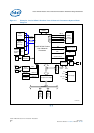
3.3.1 Signal Interface
• Intel multiplexed • Intel non-multiplexed
•Intel StrataFlash
®
• Synchronous Intel StrataFlash
®
Memory
• Motorola non multiplexed • Motorola multiplexed
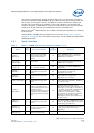
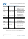
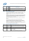
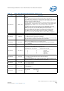
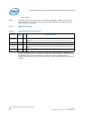
Table 5. Expansion Bus Signal Recommendations (Sheet 1 of 2)
Name
Type
Field
Pull
Up
Down
Recommendations
EX_CLK I No Use series termination resistor, 10Ω to 33Ω at the source.
EX_ALE TRI O No Use series termination resistor, 10Ω to 33Ω at the source.
EX_ADDR[23:0] I/O Yes
Use 470Ω resistors for pull-downs; required for boot strapping for initial configuration of
Configuration Register 0. Pull-ups are not required as for when the system comes out of
reset, all bits are initially set HIGH. For more details, see Table 6.
For additional details on address strapping, see the Intel
®
IXP43X Product Line of Network
Processors Developer’s Manual.
EX_WR_N I/O No Use series termination resistor, 10Ω to 33Ω at the source.
EX_RD_N I/O No Use series termination resistor, 10Ω to 33Ω at the source.