


Intel
®
IXP43X Product Line of Network Processors—Hardware Design Guidelines
Intel
®
IXP43X Product Line of Network Processors
HDG April 2007
40 Document Number: 316844; Revision: 001US
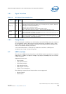
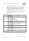
UTP_IP_DATA[5] /
ETHA_COL
IYes
UTOPIA Level 2 Mode of Operation:
UTOPIA Level 2 input data. Also known as RX_DATA.
Used by the processor to receive data from an ATM UTOPIA Level 2-compliant
PHY.
• When an NPE A is configured in UTOPIA Level 2 mode of operation and the
signal is not used, it should be pulled high through a 10-KΩ resistor.
MII Mode of Operation:
Asserted by the PHY when a collision is detected by the PHY.
• When an NPE A is configured in MII mode of operation and the signal is not
used, it should be pulled low through a 10-KΩ resistor.
When this interface is disabled through the UTOPIA Level 2 and/ or the NPE-A
Ethernet soft fuse and is not being used in a system design, it is not required for
any connection. Refer to Expansion Bus Controller chapter of the Intel
®
IXP43X
Product Line of Network Processors Developer’s Manual.
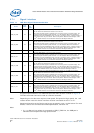
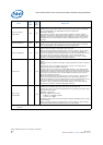
UTP_IP_DATA[6] /
ETHA_CRS
IYes
UTOPIA Level 2 Mode of Operation:
UTOPIA Level 2 input data. Also known as RX_DATA.
Used by the processor to receive data from an ATM UTOPIA Level 2-compliant
PHY.
MII Mode of Operation:
Asserted by the PHY when transmit medium or receive medium is active. De-
asserted when both the transmit and receive medium are idle. Remains asserted
throughout the duration of collision condition. PHY asserts CRS asynchronously
and de-asserts synchronously with respect to ETHA_RXCLK.
When this interface/signal is enabled and is not being used in a system design,
the interface/signal should be pulled high with a 10-KΩ resistor. When this
interface is disabled through the UTOPIA Level 2 and/or the NPE-A Ethernet soft
fuse and is not being used in a system design, it is not required for any
connection. Refer to Expansion Bus Controller chapter of the Intel
®
IXP43X
Product Line of Network Processors Developer’s Manual.
UTP_IP_DATA[7] I Yes
UTOPIA Level 2 Mode of Operation:
UTOPIA Level 2 input data. Also known as RX_DATA.
Used by the processor to receive data from an ATM UTOPIA Level 2-compliant
PHY.
MII Mode of Operation:
Not Used.
When this interface/signal is enabled and is not being used in a system design,
the interface/signal should be pulled high with a 10-KΩ resistor. When this
interface is disabled through the UTOPIA Level 2 and/or the NPE-A Ethernet soft
fuse and is not being used in a system design, it is not required for any
connection. Refer to Expansion Bus Controller chapter of the Intel
®
IXP43X
Product Line of Network Processors Developer’s Manual.
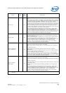
UTP_IP_ADDR[4:0] I/O No
Receive PHY address bus.
Used by the processor
while operating in an MPHY mode to poll and select a
single PHY at any given point of time.
UTP_IP_FCO TRI Yes
UTOPIA Level 2 Input Data Flow Control Output signal: Also known as the
RX_ENB_N.
In a SPHY configuration, UTP_IP_FCO is used to inform the PHY that the
processor is ready to accept data.
In MPHY configurations, UTP_IP_FCO is used to select those PHY drives that
signals UTP_RX_DATA and UTP_RX_SOC. The PHY is selected by placing the
PHY’s address on the UTP_IP_ADDR and bringing UTP_OP_FCO to logic 1 during
the current clock, followed by the UTP_OP_FCO going to a logic 0 on the next
clock cycle.
When this interface/signal is enabled and is not being used in a system design,
the interface/signal should be pulled high with a 10-KΩ resistor.
Name
Type
Field
Pull
Up/
Down
Description
†† Refer to the Intel
®
IXP43X Product Line of Network Processors Developer’s Manual for information on how to select an
interface.