


Intel
®
IXP43X Product Line of Network Processors—Hardware Design Guidelines
Intel
®
IXP43X Product Line of Network Processors
HDG April 2007
32 Document Number: 316844; Revision: 001US
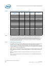
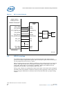
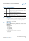
3.6 GPIO Interface
The IXP43X network processors provide 16 general-purpose input/output pins to
generate and capture application-specific input and output signals. Each individual pin
can be programmed as an input or output.
When programmed as an input, GPIO 0 to GPIO 12 can be configured to be an interrupt
source. Interrupt sources can be configured to detect either active high, active low,
rising edge, falling edge, or transitional. In addition, GPIO14 and GPIO15 can be
programmed to provide a user-programmable clock out.
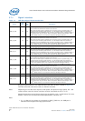
During reset, all pins are configured as inputs and remain in this state until configured
otherwise, with the exception of GPIO15, which by default provides a clock output. The
driver strength of GPIO pins is sufficient to drive external LEDs with a proper limiting
resistor.
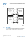
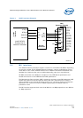
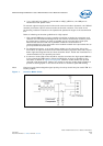
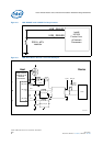
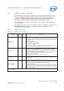
Figure 6. MII Interface Example
Intel® IXP43X
Product Line of
Network Processors
MII Interface
ETH_RXDATA[3:0]
ETH_TXDATA[3:0]
ETH_TXCLK
ETH_RXDV
ETH_COL
ETH_MDIO
ETH_MDC
Magnetics RJ45
25 MHz
ETH_RXCLK
ETH_CRS
ETH_TXEN
RXDATA[3:0]
TXDATA[3:0]
TXCLK
RXDV
COL
MDIO
MDC
RXCLK
TXEN
10/100
PHY
CRS
VCC (3.3 V)
B4101-004
1.5 KΩ