


Intel
®
IXP43X Product Line of Network Processors—Hardware Design Guidelines
Intel
®
IXP43X Product Line of Network Processors
HDG April 2007
18 Document Number: 316844; Revision: 001US
3.2 DDRII/I SDRAM Interface
The IXP43X network processors support unbuffered, DDRI-266 or DDRII-400 SDRAM
technology, capable of addressing two memory banks (one bank per CS). Each bank
can be configured to support 32/64/128/256/512-Mbyte for a total combined memory
support of 1 Gbyte.
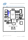
The IXP43X network processors integrate a high-performance, multi-ported Memory
Controller Unit (MCU) to provide a direct interface with its local memory subsystem.
The MCU supports:
• DDR II/I or DDRII-400 SDRAM
• 128/256/512-Mbit, 1-Gbit DDRI SDRAM technology support
• Supports 256/512-Mbit technologies for the DDRII-400
• Only unbuffered DRAM support (No registered DRAM support)
• Dedicated port for Intel XScale processor to the DDRII/DDRI SDRAM
• Between 32 MBs and 1-GB of 32-bit DDRI SDRAM
• Between 64MBs and 512 MBs of 32-bit DDRII SDRAM
• 16MB for 16-bit memory systems for DDRI SDRAM (non-ECC) supporting 128-Mbit
technology only
• 32MB for 16-bit memory systems for DDRII SDRAM (non-ECC) supporting 256-Mbit
technology only
• Single-bit error correction, multi-bit detection support (ECC)
• 32-bit, 40-bit wide memory interfaces (non-ECC and ECC support), and 16-bit wide
memory interfaces (non-ECC)
The DDRII/DDRI SDRAM interface provides a direct connection to a high-bandwidth
and reliable memory subsystem. The DDRII/DDRI SDRAM interface is a 16 or
32-bit-wide data path.
The device supports non-ECC and ECC for error correction, which can be enable or
disable by software as required. Banks have a bus width of 32 bits for non ECC or
40 bits for ECC enable (32-bit data + 8-bit ECC).
An 8-bit Error Correction Code (ECC) across each 32-bit word improves system
reliability. It is important to note that ECC is also referred to as CB in many DIMM
specifications. The pins on the IXP43X network processors are called
DDR_CB[7:0]. ECC is only implemented in the 32-bit mode of operation, while the
algorithm used to generate the 8-bit ECC is implemented over 64-bit.
The ECC circuitry is designed to operate always on a 64-bit data and when operating in
32-bit mode, the upper 32 bits are driven to zeros internally. To summarize the impact
to the customer, the full 8 bits of ECC is stored and read from a memory array for the
ECC logic to work. An 8-bit-wide memory is used when implementing ECC.
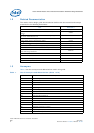
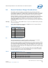
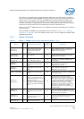
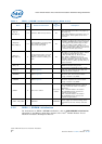
ETHERNET Can enable MII MACs. Enable of MACs can be separately done per each NPE.
USB Host Each USB can be Enable separately.
DDR ECC ECC can be enabled or disabled separately from the rest of the DDR interface.
Table 3. Soft Fusible Features (Sheet 2 of 2)
Name Description