


Intel
®
IXP43X Product Line of Network Processors—Hardware Design Guidelines
Intel
®
IXP43X Product Line of Network Processors
HDG April 2007
64 Document Number: 316844; Revision: 001US
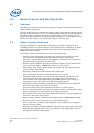
— Be aware of propagation delays between a microstrip and stripline.
— Calculate capacitive loading of all components and properly compensate with a
series or parallel terminations.
• Measure and match trace lengths for devices that interface with each other and
have their clock derived from the same source.
If traces must be long, treat them as transmission lines. Terminate clock traces to
match trace impedance.
• If there is a power plane, instead of a ground plane, make sure that the power
plane has adequate decoupling to ground, especially near clock drivers and
receivers.
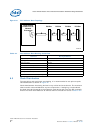
5.2.3 MII Signal Considerations
MII signals run at 25 MHz and the required routing guide lines are as follows:
• Minimize the number of vias to two per trace
• Keep traces as short as possible and straight, away from other signals
• Control impedance to maintain at 50 Ω
• the length of Rx or Tx in each group must match
• Avoid sharp corners, using 45° corners instead
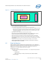
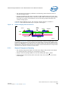
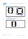
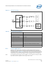
5.2.4 USB V2.0 Considerations
The following are recommendations for routing differential pair signal required to by
the USB interface:
• Traces can be routed in tightly couple structure with 5mil trace width and 10mil air
gap, or maintain air gap equal 2X trace width. It is recommended to route
manually.
• Match trace length for each differential pair.
• Avoid sharp corners, use 45° corners instead.
• Always use a perfect symmetry within a differential pair.
• Minimize the number vias.
• Avoid routing other signals close by or in parallel to the differential pair,
maintaining no less than 50 mil to any other signal.
• Maintain control impedance for each differential pair to 90 Ω +/- 15 Ω.
• Use high value ferrite beads (100 MHz/60 Ω – 100 MHz/240 Ω).
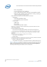
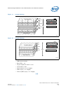
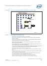
5.2.5 Crosstalk
Crosstalk is caused by capacitance and inductance coupling between signals. It is
composed of both backward and forward crosstalk components.
Backward crosstalk creates an induced signal on the network that propagates in the
opposite direction of the aggressor signal. Forward crosstalk creates a signal that
propagates in the same direction as the aggressor signal.
Circuit board analysis software should be used to analyze your board layout for
crosstalk problems.
• To effectively route signals on the PCB, signals are grouped (address, data, and so
on.).
— The space between groups can be 3 w (where w is the width of the traces).