


Intel
®
IXP43X Product Line of Network Processors
April 2007 HDG
Document Number: 316844; Revision: 001US 51
Hardware Design Guidelines—Intel
®
IXP43X Product Line of Network Processors
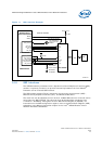
3.12.1 Signal Interface
3.13 Input System Clock
The IXP43X network processors require a 33.33-MHz reference clock to generate all
internal clocks required including core clock and the various buses running internally
within the system.
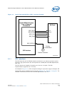
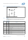
3.13.1 Clock Signals
3.13.2 Clock Oscillator
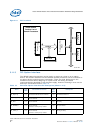
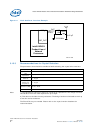
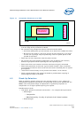
While using an external clock oscillator to supply the 33.33-MHz reference system
clock, connect the clock oscillator output to the OSC_IN pin through a series
termination of 33 Ω as shown in Figure 14. The series termination helps to smooth the
rise and fall edges of the clock and eliminate ringing. Leave the OSC_OUT pin
unconnected.
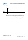
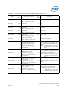
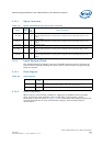
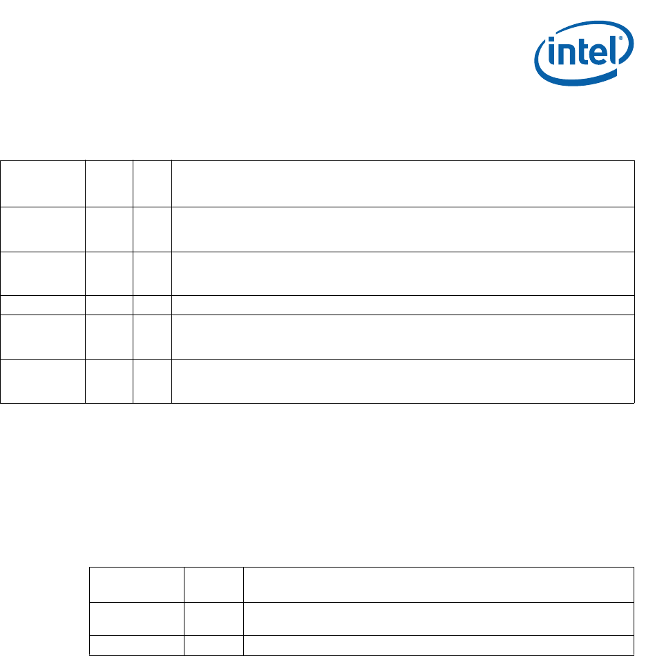
Table 19. Synchronous Serial Peripheral Port Interface
Name
Type
Field
Pull
Up/
Down
Recommendations
JTG_TMS I Yes
Test mode select.
When the JTAG interface is not being used, the signal must be pulled high using a 10-kΩ
resistor.
JTG_TDI I Yes
Test Input data.
When the JTAG interface is not being used, the signal must be pulled high using a 10-kΩ
resistor.
JTG_TDO O O Test Output data.
JTG_TRST_N I Yes
Test Reset.
When the JTAG interface is not being used, the signal must be pulled low using a 10-kΩ
resistor.
JTG_TCK I Yes
Test Clock.
When the JTAG interface is not being used, the signal must be pulled high using a 10-kΩ
resistor.
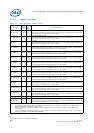
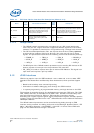
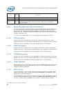
Table 20. Clock Signals
Name
Type
Field
Description
OSC_IN I
Source must be a clock input of 33.33-MHz.
Use a series termination resistor, 10 Ω to 33 Ω at the source.
OSC_OUT O No connect