


99
CHAPTER 3 SPECIFICATIONS
3
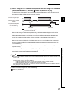
3.4 Buffer Memory Assignment
3.4.2 Details of the buffer memory
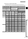
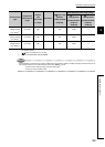
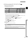
*1 When the input range is changed, the set values in some buffer memory areas are initialized automatically and return to
the default value (0).
( Page 101, Section 3.4.2 (12) (d))
*2 Same as the Q64TCRTN, Q64TCRTBWN
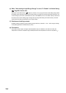
Remark
For the following control mode and channel, CH Input range (Un\G32, Un\G64, Un\G96, Un\G128) cannot be set to 201 to
205. If these values are set, a write data error (error code: 4
H
) occurs.
• CH3 and CH4 in heating-cooling control (normal mode)
• CH2 in mix control (normal mode)
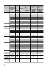
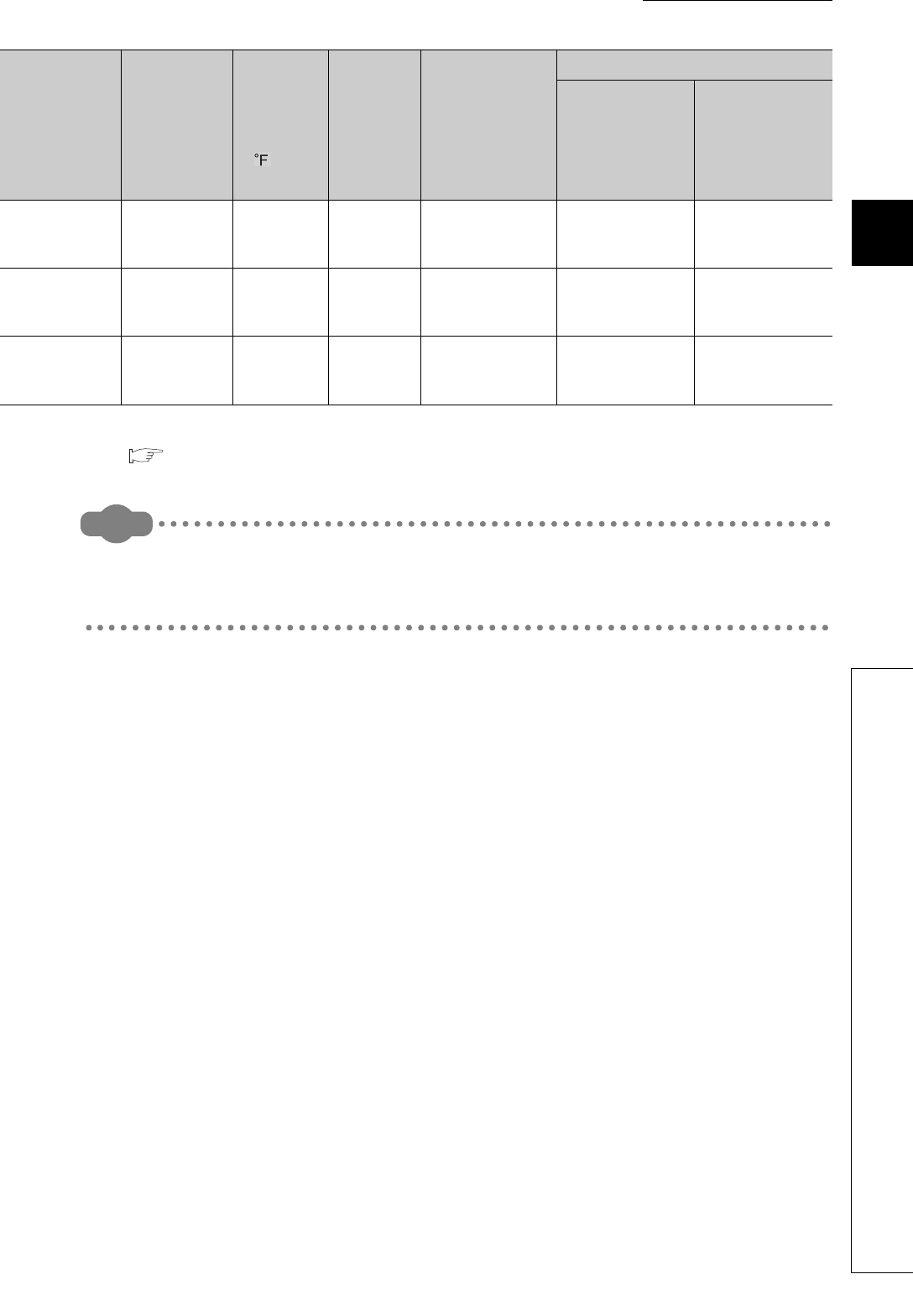
Input from other
analog modules
(0 to 16000)
*2
0 to 16000 digit 1 203 16000 0
Input from other
analog modules
(0 to 20000)
*2
0 to 20000 digit 1 204 20000 0
Input from other
analog modules
(0 to 32000)
*2
0 to 32000 digit 1 205 32000 0
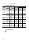
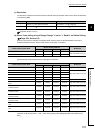
Thermocouple
type
Temperature
measurement
range
Celsius
(°C)/
Fahrenheit
( )/digit
Resolution
CH Input range
(Un\G32,
Un\G64, Un\G96,
Un\G128)
Auto-setting at input range change
*1
CH Upper limit
setting limiter
(Un\G55, Un\G87,
Un\G119,
Un\G151)
CH Lower limit
setting limiter
(Un\G56, Un\G88,
Un\G120,
Un\G152)