


105
CHAPTER 3 SPECIFICATIONS
3
3.4 Buffer Memory Assignment
3.4.2 Details of the buffer memory
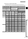
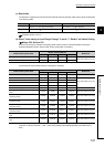
(15)CH Proportional band (P) setting (Un\G35, Un\G67, Un\G99, Un\G131)
CH Heating proportional band (Ph) setting (Un\G35, Un\G67, Un\G99,
Un\G131)
CH Cooling proportional band (Pc) setting (Un\G720, Un\G736, Un\G752,
Un\G768)
Set proportional band (P)/heating proportional band (Ph)/cooling proportional band (Pc) to perform PID control.
(In the heating-cooling control, set heating proportional band (Ph) to Un\G35, Un\G67, Un\G99, Un\G131.)
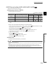
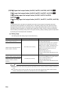
(a) Setting range
Set the value within the following ranges for the full scale of the set input range. ( Page 96, Section 3.4.2
(12))
• Proportional band (P) setting: 0 to 10000 (0.0% to 1000.0%)
• Heating proportional band (Ph) setting: 0 to 10000 (0.0% to 1000.0%)
• Cooling proportional band (Pc) setting: 1 to 10000 (0.1% to 1000.0%)
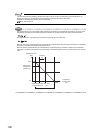
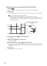
Ex.
When the value of the buffer memory is set as follows, the proportional band (P) is 60°C.
•CH Input range (Un\G32, Un\G64, Un\G96, Un\G128): 38 (temperature measurement range: -200.0 to
400.0°C)
•CH Proportional band (P) setting (Un\G35, Un\G67, Un\G99, Un\G131): 100 (10.0%)
(Full scale) × (Proportional band (P) setting) = (400.0°C - (-200.0)) × 0.1 = 60°C
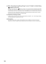
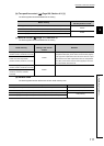
(b) Two-position control
Set the proportional band (P)/heating proportional band (Ph) to 0.
For details on control methods, refer to the following.
Page 166, Section 4.3
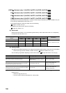
(c) Default value
The default values are set to 30 (3.0%) in all channels.
Standard
Heating-cooling
Heating-cooling