


51
CHAPTER 3 SPECIFICATIONS
3
3.3 I/O Signals Transferred to/from the CPU Module
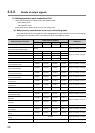
3.3.2 Details of input signals
The conditions whether to perform the temperature judgment, PID control, and alert judgment by the Q64TCN differ among
the following timings.
• Setting mode at power-ON
• Operation mode (in operation)
• Setting mode (after operation)
For each detail on the temperature judgment, PID control, and alert judgment, refer to the following.
• Temperature judgment: Page 87, Section 3.4.2 (3)
• PID control: Page 170, Section 4.3 (6)
• Alert judgment: Page 203, Section 4.12 (5)
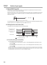
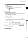
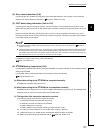
(3) Write error flag (Xn2)
The write data error occurs in the Q64TCN when the data is set to the buffer memory in the area where data
cannot be written or the timing when data cannot be written.
After a write data error occurs and the error code is stored in Write data error code (Un\G0), this flag turns on.
A write data error occurs under the following conditions.
• When data is set in the buffer memory of the system area
• When the setting of the area which can be written only during the setting mode (Setting/operation mode
status (Xn1): OFF) is changed during the operation mode (Setting/operation mode status (Xn1): ON)
( Page 50, Section 3.3.2 (2))
• When the data which cannot be set is set
• When the setting of the buffer memory is changed during the default setting registration ( Page 58,
Section 3.3.3 (5))
• When the current control mode and the control mode backed up in the E
2
PROM are different due to the
change of the control mode selection.
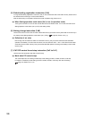
(4) Hardware error flag (Xn3)
This flag turns on when hardware error occurs in the Q64TCN.
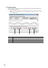
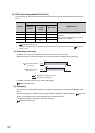
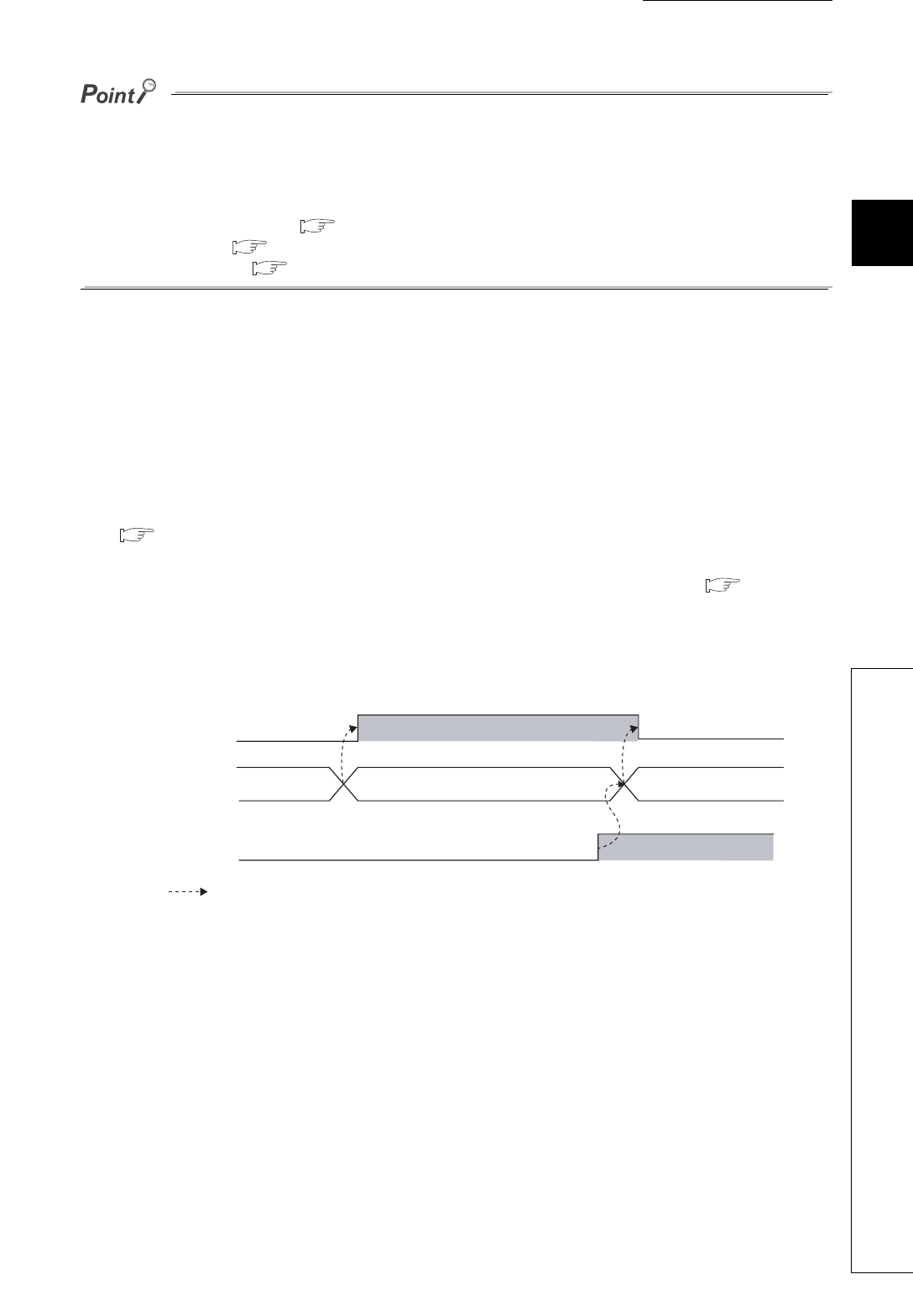
Write error flag (Xn2)
Write data error code
(Un\G0)
Error reset instruction (Yn2)
OFF
OFF
ON
ON
Error code
0
H
0
H
Executed by the Q64TCN