


368
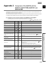
*1 The address where the error occurred is stored in
H
.
Buffer memory addresses are written in decimal (Intelligent function module device (Un\G)) in this manual. Read the
stored value as a decimal value and refer to the buffer memory list ( Page 59, Section 3.4.1).
*2 The buffer memory areas checked are Un\G0 to Un\G287. No error occurs for writes in the system area in or after
Un\G288.
*3 For the writable area in setting mode, refer to the buffer memory list ( Page 59, Section 3.4.1).
*4 "In the operation mode" refers to one of the following states.
• When Setting/operation mode instruction (Yn1) or Setting/operation mode status (Xn1) is on.
• When Setting/operation mode instruction (Yn1) turns on and off and PID continuation flag (Un\G169) is set to Continue
(1).
*5 When an error occurs in CH1 Alert 1 mode setting (Un\G192) and CH1 Alert 2 mode setting (Un\G193), 0C0
H
(hex) in the buffer memory address with the smallest number "Un\G192" is stored in Error code (Un\G0).
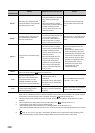
5
H
*1
The setting of the upper/lower limit
value output limiter or the upper/lower
limit setting limiter is invalid.
• The data written is retained.
• Change the setting to an allowable
value for the upper/lower limit
value.
• When data is written to multiple
system areas, the address with the
smallest number of the buffer
memory area where an error was
detected is stored.
*5
Set the value where the upper limit
value is greater than the lower limit
value.
6
H
*1
The setting value is being changed
while Default setting registration
instruction (Yn9) was on.
• The data written is ignored.
• The setting cannot be changed until
an error reset is performed.
• The content of Write data error
code (Un\G0) does not change
even if another write error occurs.
After turning off, on, and off Error reset
instruction (Yn2), change the setting
value.
7
H
*1
2-point sensor compensation setting
is invalid.
• The data written is retained.
• When data is written to multiple
system areas, the address with the
smallest number of the buffer
memory area where an error was
detected is stored.
*5
• When both the offset value and
gain value are within the input
range and the offset value is
greater than or equal to the gain
value, the gain value address is
stored as the address where the
error occurred.
• Enter the temperature within the
input range.
• Set the values so that the 2-point
sensor compensation offset value
(measured value) is smaller than the
2-point sensor compensation gain
value (measured value) and the 2-
point sensor compensation offset
value (compensation value) is
smaller than the 2-point sensor
compensation gain value
(compensation value).
A
H
An alarm has occurred.
Refer to the alarm code list ( Page 370, Section 8.7).
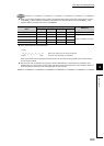
001E
H
Set value discrepancy error
The current control mode and the
control mode backed up in the
E
2
PROM are different due to the
change of the control mode selection.
• The set value cannot be changed
until the control mode is
determined.
• The buffer memory data reverts to
the default value for the selected
control mode.
Turn the E
2
PROM backup instruction
(Yn8) OFF ON OFF.
000F
H
Values set in the intelligent function
module switch setting are those
outside the setting range.
The RUN LED turns off, the ERR.
LED turns on, and the module does
not operate.
Set the correct values on the intelligent
function module switch setting.
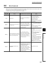
Error code
(hexadecimal)
Cause Operation at error occurrence Action
Ex.