


139
CHAPTER 3 SPECIFICATIONS
3
3.4 Buffer Memory Assignment
3.4.2 Details of the buffer memory
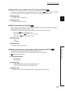
(54)CT CT input channel assignment setting (Un\G264 to Un\G271)
Set the assignment of each current sensor (CT) input to the channels.
(a) Supported modules
• Q64TCTTBWN
•Q64TCRTBWN
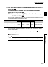
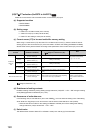
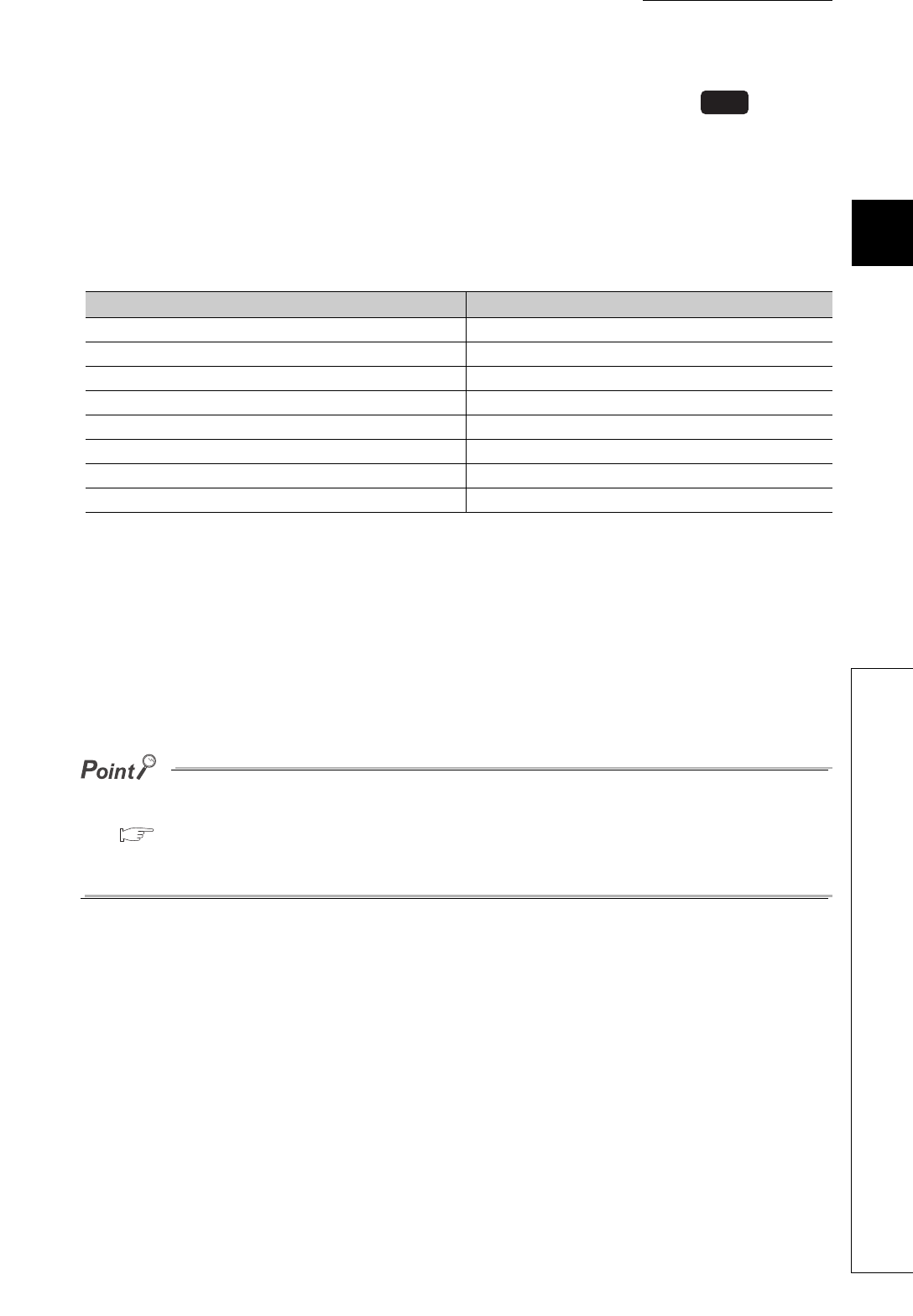
(b) Correspondence between CT input terminal and buffer memory address
(c) Setting range
• 0: Unused
• 1: CH1
• 2: CH2
• 3: CH3
• 4: CH4
(d) Default value
The default values are set to Unused (0) for all terminals.
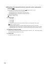
● If a three-phase heater is used, the same channel should be assigned to two current sensor (CT) inputs.
For setting examples, refer to the following.
Page 296, Section 5.4.3
● In the heating-cooling control, CH3 and CH4 cannot be assigned to this setting.
In the mix control, CH2 cannot be assigned to this setting.
CT input terminal Buffer memory address
CT1 Un\G264
CT2 Un\G265
CT3 Un\G266
CT4 Un\G267
CT5 Un\G268
CT6 Un\G269
CT7 Un\G270
CT8 Un\G271
Common