


371
CHAPTER 8 TROUBLESHOOTING
8
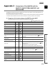
8.7 Alarm Code List
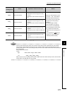
*1 represents the number of the channel (1
H
to 4
H
) where the alarm occurred.
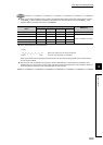
Remark
• The error code is always given priority over the alarm code for being stored in Write data error code (Un\G0).
For that reason, when an alarm occurs during an error, the alarm code is not stored in Write data error code
(Un\G0). Further, when an error occurs during an alarm, the error code is written over the alarm code in Write data
error code (Un\G0).
• Alarm priorities are as follows.
When an alarm occurs, if its priority is the same as or higher than that of alarms already occurred, the new alarm
code is written over Write data error code (Un\G0).
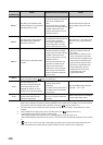
06A
H
Alert 1 has occurred.
• The ALM LED turns on.
•CH Alert occurrence flag (XnC to XnF)
turns on.
•CH Alert 1 (b8 of Un\G5 to Un\G8) turns
on.
When Error reset instruction (Yn2) is
turned OFF ON OFF after the
temperature process value (PV) is
restored after going into alert status,
Write data error code (Un\G0) is
cleared to 0.
The following flags and buffer
memory bits that turn on when an
alarm occurs turn off automatically
when the temperature process value
(PV) is restored from alert status.
•CH Alert occurrence flag (XnC to
XnF)
• The applicable bit ( Page 87,
Section 3.4.2 (3)) of CH Alert
definition (Un\G5 to Un\G8)
07A
H
Alert 2 has occurred.
• The ALM LED turns on.
•CH Alert occurrence flag (XnC to XnF)
turns on.
•CH Alert 2 (b9 of Un\G5 to Un\G8) turns
on.
08A
H
Alert 3 has occurred.
• The ALM LED turns on.
•CH Alert occurrence flag (XnC to XnF)
turns on.
•CH Alert 3 (b10 of Un\G5 to Un\G8) turns
on.
09A
H
Alert 4 has occurred.
• The ALM LED turns on.
•CH Alert occurrence flag (XnC to XnF)
turns on.
•CH Alert 4 (b11 of Un\G5 to Un\G8) turns
on.
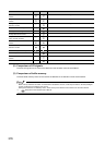
Priority
High
01A
H
, 02A
H
, 03A
H
, 04A
H
, 05A
H
Low
06A
H
, 07A
H
, 08A
H
, 09A
H
,
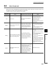
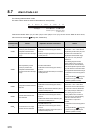
Alarm code
(hexadecimal)
*1
Cause Operation at alarm occurrence Action