


59
CHAPTER 3 SPECIFICATIONS
3
3.4 Buffer Memory Assignment
3.4.1 Q64TCN buffer memory assignment list
3.4 Buffer Memory Assignment
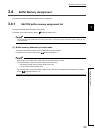
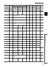
This section describes the Q64TCN buffer memory assignment.
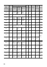
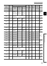
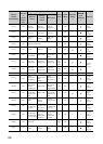
3.4.1 Q64TCN buffer memory assignment list
This section lists the Q64TCN buffer memory areas.
For details on the buffer memory, refer to Page 86, Section 3.4.2.
Do not write data in the system area or the write-protect area in a sequence program in the buffer memory. Doing so may
cause malfunction.
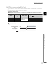
(1) Buffer memory address by control mode
This section describes the buffer memory assignments by control mode.
For details on the control mode, refer to Page 162, Section 4.1.
Depending on the control mode, some channels cannot be used for control.
The channels which cannot be used for control are the following.
• For heating-cooling control (normal mode): CH3, CH4
• For mix control (normal mode): CH2
The channels which cannot be used for control can be used only for temperature measurement. For details,
refer to Page 262, Section 4.27.