


67
CHAPTER 3 SPECIFICATIONS
3
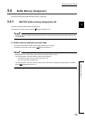
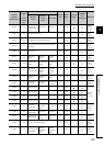
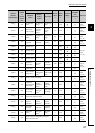
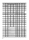
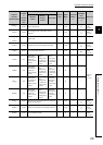
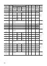
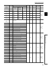
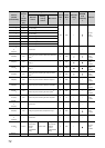
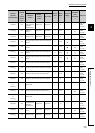
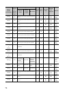
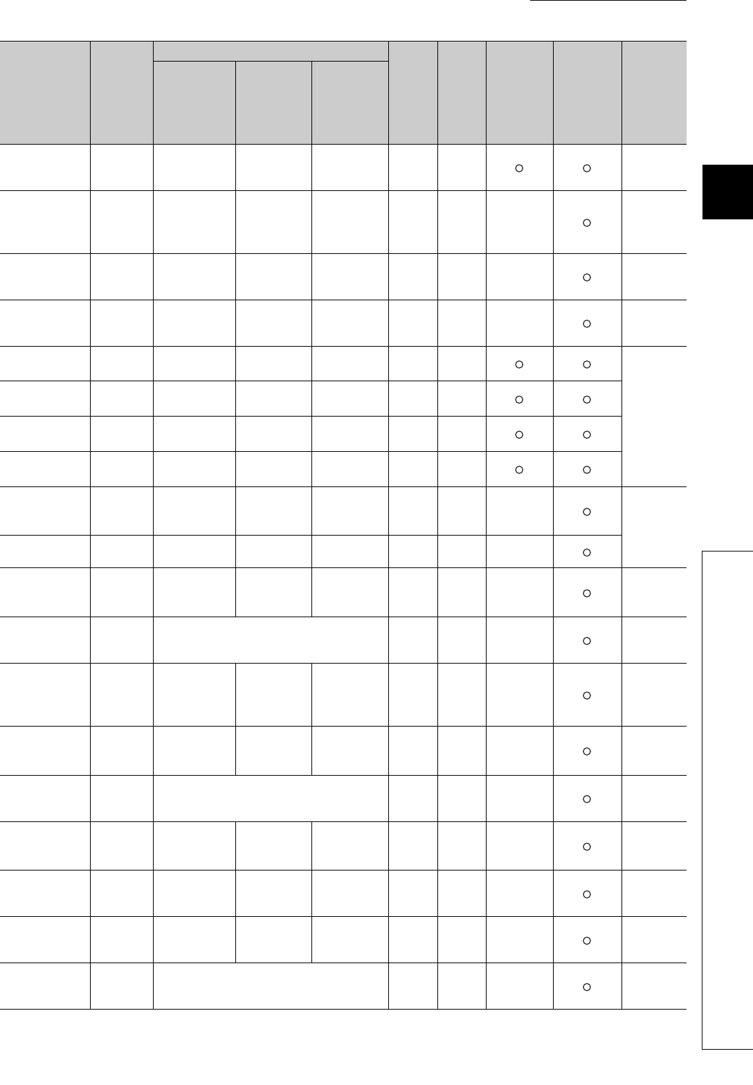
3.4 Buffer Memory Assignment
3.4.1 Q64TCN buffer memory assignment list
130(82
H
)
CH4
Set value (SV)
setting
Set value (SV)
setting
*6
Set value (SV)
setting
0R/W
Page 104,
Section
3.4.2 (14)
131(83
H
)
CH4
Proportional
band (P) setting
Heating
proportional
band (Ph)
setting
*6
Proportional
band (P)
setting
30 R/W ×
Page 105,
Section
3.4.2 (15)
132(84
H
)
CH4
Integral time (I)
setting
Integral time (I)
setting
*6
Integral time (I)
setting
240 R/W ×
Page 107,
Section
3.4.2 (16)
133(85
H
)
CH4
Derivative time
(D) setting
Derivative time
(D) setting
*6
Derivative time
(D) setting
60 R/W ×
Page 107,
Section
3.4.2 (17)
134(86
H
)
CH4 Alert set value 1
Alert set value
1
*6
Alert set value
1
0R/W
Page 108,
Section
3.4.2 (18)
135(87
H
)
CH4 Alert set value 2
Alert set value
2
*6
Alert set value
2
0R/W
136(88
H
)
CH4 Alert set value 3
Alert set value
3
*6
Alert set value
3
0R/W
137(89
H
)
CH4 Alert set value 4
Alert set value
4
*6
Alert set value
4
0R/W
138(8A
H
)
CH4
Upper limit
output limiter
Heating upper
limit output
limiter
*6
Upper limit
output limiter
1000 R/W ×
Page 110,
Section
3.4.2 (19)
139(8B
H
)
CH4
Lower limit
output limiter
System area
Lower limit
output limiter
0R/W ×
140(8C
H
)
CH4
Output variation
limiter setting
Output
variation limiter
setting
*6
Output
variation limiter
setting
0R/W ×
Page 112,
Section
3.4.2 (20)
141(8D
H
)
CH4 Sensor correction value setting 0 R/W ×
Page 113,
Section
3.4.2 (21)
142(8E
H
)
CH4
Adjustment
sensitivity (dead
band) setting
Adjustment
sensitivity
(dead band)
setting
*6
Adjustment
sensitivity
(dead band)
setting
5R/W ×
Page 113,
Section
3.4.2 (22)
143(8F
H
)
CH4
Control output
cycle setting
Heating control
output cycle
setting
*6
Control output
cycle setting
30 R/W ×
Page 114,
Section
3.4.2 (23)
144(90
H
)
CH4 Primary delay digital filter setting 0 R/W ×
Page 115,
Section
3.4.2 (24)
145(91
H
)
CH4
Control
response
parameters
Control
response
parameters
*6
Control
response
parameters
0R/W ×
Page 116,
Section
3.4.2 (25)
146(92
H
)
CH4
AUTO/MAN
mode shift
AUTO/MAN
mode shift
*6
AUTO/MAN
mode shift
0R/W ×
Page 117,
Section
3.4.2 (26)
147(93
H
)
CH4
MAN output
setting
MAN output
setting
*6
MAN output
setting
0R/W ×
Page 118,
Section
3.4.2 (27)
148(94
H
)
CH4
Setting change rate limiter/Setting change rate
limiter (temperature rise)
*10
0R/W ×
Page 119,
Section
3.4.2 (28)
Address
(decimal
(hexadecimal))
Target
channel
or
current
sensor
(CT)
Setting contents
Default
value
*1
Read/
Write
*2
Automatic
setting
*3
E
2
PROM
write
availability
*4
Reference
Standard
control
Heating-
cooling
control
Mix control