


319
CHAPTER 7 PROGRAMMING
7
7.2 When Using the Module in a Standard System Configuration
7.2.2 Standard control (peak current suppression function, simultaneous temperature rise function)
7.2.2 Standard control (peak current suppression function,
simultaneous temperature rise function)
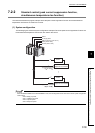
This section describes the program example where the peak current suppression function and the simultaneous
temperature rise function are used for the control.
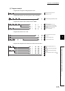
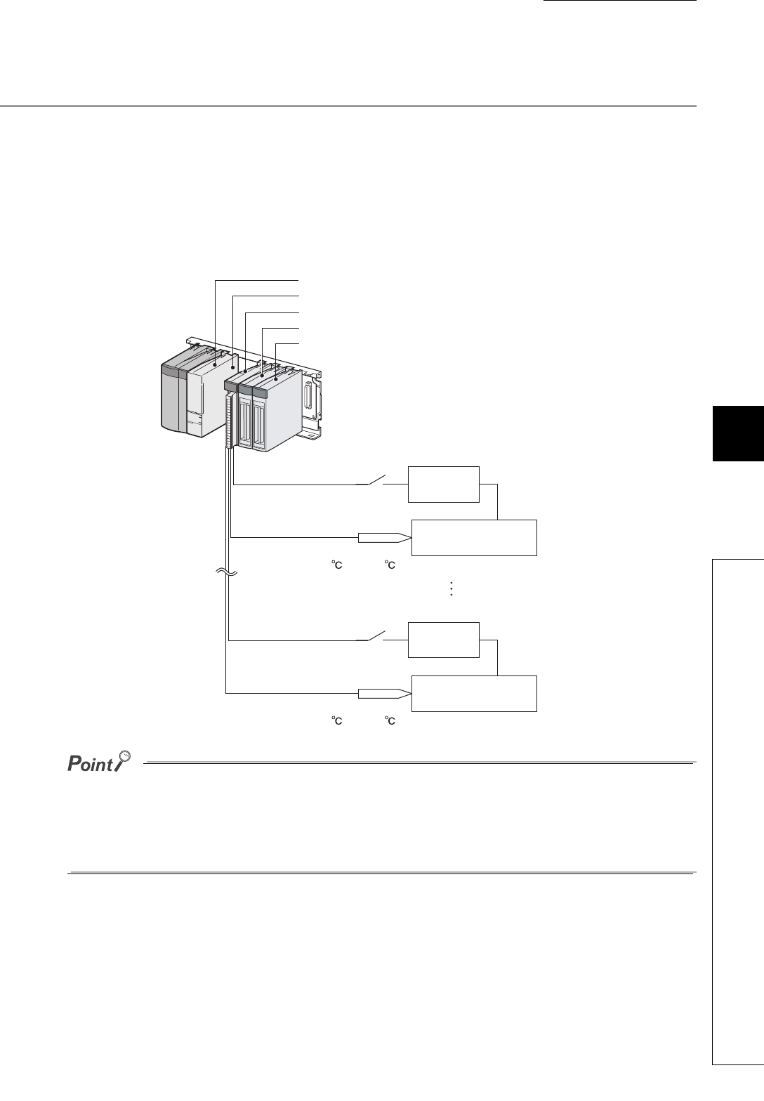
(1) System configuration
The following figure shows the system configuration example of when the peak current suppression function and
the simultaneous temperature rise function are used for the control.
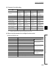
When the Q64TCTTBWN or the Q64TCRTBWN is used, the I/O assignment is the same as that of the system configuration
shown above.
• Slot 0: Empty 16 points
• Slot 1: Intelligent 16 points
• Slot 2: Input 64 points
• Slot 3: Output 64 points
QY42P (Y60 to Y9F)
QX42 (X20 to X5F)
QCPU
Q64TCTTN (X/Y10 to X/Y1F)
16 empty points
Type-K thermocouple
0 to 1300
Heater
CH1
Object to be controlled
CH4
Object to be controlled
Type-K thermocouple
0 to 1300
Heater