


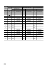
290
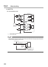
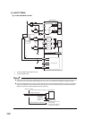
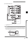
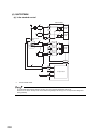
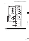
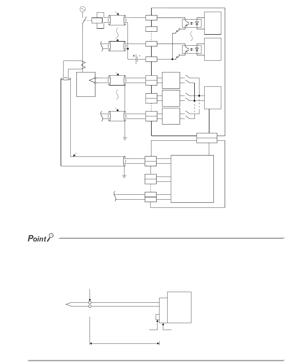
(2) Q64TCTTBWN
(a) In the standard control
*1 Use the shielded compensation lead wire.
*2 Use the shielded cable.
● To use the heater disconnection detection function, the CT input channel assignment must be set. Since the CT1 is used
in the loop of CH1 in the above wiring example, set CH1(1) to CT1 CT input channel assignment setting (Un\G264).
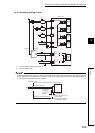
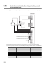
● Use the compensation lead wire for the cable of thermocouple. If the compensation lead wire is not used, and when the
cold junction temperature compensation resistor is away from the end tip of thermocouple, the (ambient) temperature
difference may lead to a faulty temperature process value (PV).
L1
L2
L4
COM-
Q64TCTTBWN
CH1+
CH1-
CH2+
CH2-
CH4+
CH4-
CT1
CT1
CT2
CT2
24VDC
Current sensor
(CT)
CT input circuit
Controlled
object
Internal
circuit
Internal
circuit
Internal
circuit
Filter
Filter
Filter
Connector
Connector
*2
*1
*1
*2
*2
CT8
CT8
Q64TCTT(BW)N
Reference junction
Thermocouple extension wire (OK)
Shielded cable (NG)
Cold junction
temperature
compensation
resistor
(Ambient) temperature difference
Terminal block
A: Reference junction of the
thermocouple
B: Cold junction temperature
compensation resistor
A
B