S/UNI-QUAD
PMC-Sierra, Inc.
PM5349 S/UNI-QUAD
DATASHEET
PMC-971239 ISSUE 6 SATURN USER NETWORK INTERFACE (155-QUAD)
Proprietary and Confidential to PMC-Sierra, Inc., and for its Customers’ Internal Use
30
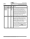
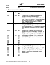
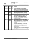
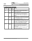
Pin Name Type Pin
No.
Function
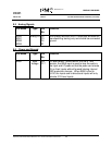
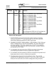
AVS Analog
Ground
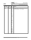
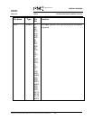
F3
A3
D5
H3
K3
K4
T4
N3
P1
W4
AC3
Y5
L2
M3
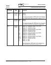
RAVS1_A - Channel #1 PECL Input Buffer
RAVS1_B - Channel #1 CRU
RAVS1_C - Channel #1 CRU
RAVS2_A - Channel #2 PECL Input Buffer
RAVS2_B - Channel #2 CRU
RAVS2_C - Channel #2 CRU
RAVS3_A - Channel #3 PECL Input Buffer
RAVS3_B - Channel #3 CRU
RAVS3_C - Channel #3 CRU
RAVS4_A - Channel #4 PECL Input Buffer
RAVS4_B - Channel #4 CRU
RAVS4_C - Channel #4 CRU
TAVS1_A - CSU
TAVS1_B - CSU
The analog ground (AVS) pins for the analog core.
AVS should be connected to analog GND.
Notes on Pin Description:
1. All S/UNI-QUAD inputs and bi-directionals present minimum capacitive
loading and operate at TTL logic levels except: the SD, RXD+ and RXD-
inputs which operate at pseudo-ECL (PECL) logic levels
2. The RDAT[7:0], RPRTY, RSOC, DRCA4-1, RCA, DTCA4-1, TCA, TCLK and
RCLK1-4 outputs have a 4 mA DC drive capability. The TDO output has a 1
mA drive capability. All the other outputs have a 2 mA DC drive capability.
The TXD+ and TXD- outputs are met to be terminated in a passive network
and interface at PECL levels.
3. It is mandatory that every ground pin (VSS) be connected to the printed
circuit board ground plane to ensure a reliable device operation.
4. It is mandatory that every power pin (VDD) be connected to the printed circuit
board power plane to ensure a reliable device operation.
5. All analog power and ground can be sensitive to noise. They must be
isolated from the digital power and ground. Care must be taken to decouple
these pins from each other and all other analog power and ground pins.


