S/UNI-QUAD
PMC-Sierra, Inc.
PM5349 S/UNI-QUAD
DATASHEET
PMC-971239 ISSUE 6 SATURN USER NETWORK INTERFACE (155-QUAD)
Proprietary and Confidential to PMC-Sierra, Inc., and for its Customers’ Internal Use
70
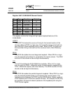
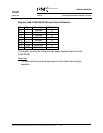
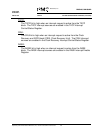
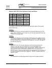
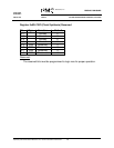
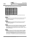
Register 0x07: S/UNI-QUAD Channel Control
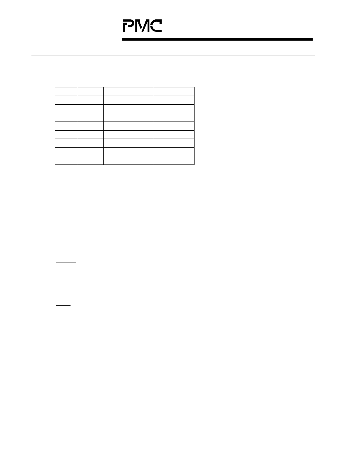
Bit Type Function Default
Bit 7 R/W TFPI_EN 0
Bit 6 R/W Reserved 0
Bit 5 R/W RXDINV 0
Bit 4 Unused X
Bit 3 R/W PDLE 0
Bit 2 R/W LLE 0
Bit 1 R/W SDLE 0
Bit 0 R/W LOOPT 0
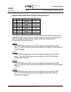
This register controls the timing and high speed loopback features of the
S/UNI-QUAD.
LOOPT:
The LOOPT bit selects the source of timing for the transmit section of the
channel. When LOOPT is a logic zero, the transmitter timing is derived from
input REFCLK (Clock Synthesis Unit) is used. When LOOPT is a logic one,
the transmitter timing is derived from the recovered clock. (Clock Recovery
Unit).
SDLE:
The SDLE bit enables the serial diagnostic loopback. When SDLE is a logic
one, the transmit serial stream is connected to the receive stream. The SDLE
and the LLE bits should not be set high simultaneously.
LLE:
The LLE bit enables the S/UNI-QUAD line loopback. When LLE is a logic
one, the value on RXD+/- differential inputs is synchronously mapped to the
TXD+/- differential outputs, after clock recovery. The SDLE and the LLE bits
should not be set high simultaneously.
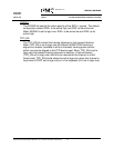
PDLE:
The PDLE bit enables the parallel diagnostic loopback. When PDLE is a logic
one, the transmit parallel stream is connected to the receive stream. The
loopback point is between the TPOP and the RPOP blocks. Blocks upstream
of the loopback point continue to operate normally. For example line AIS may
be inserted in the transmit stream upstream of the loopback point using the
TSOP Control register.


