Chapter 5 Programming Considerations
© National Instruments Corporation 5-23 VXI-MXI User Manual
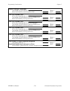
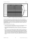
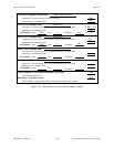
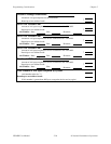
4. Figure 5-17 is the worksheet for MXIbus #3, which includes VXIbus Mainframes #4 and #5.
Mainframe #4 needs 2 KB and Mainframe #5 needs 1 KB of A16 space. We fill in the
appropriate spaces on the worksheet.
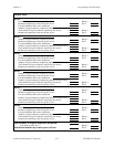
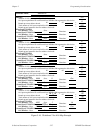
5. Now we return to Figure 5-16 and fill in the MXIbus #3 information in the space for a
second-level MXIbus link connected to VXIbus Mainframe #3. MXIbus #3 needs 2 KB for
Mainframe #4 and 1 KB for Mainframe #5. The sum is 3 KB, which rounds up to the next
address break of 4 KB. The amount of A16 space required for the window into VXIbus
Mainframe #3 is 4 KB plus the 3 KB required by MXIbus #3, which rounds up to the next
address break of 8 KB. We enter all of these numbers into the worksheet.
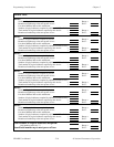
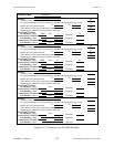
6. We now fill in Figure 5-15 for MXIbus #1. MXIbus #1 requires 512 bytes for MXIbus
Device A and 8 KB for VXIbus Mainframe #3. The sum of these values rounds up to the
nearest address break of 16 KB. We record this information on the worksheet.
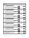
7. Figure 5-15 is now completed for MXIbus #2. The only device on MXIbus #2 is VXIbus
Mainframe #6, which needs 2 KB of A16 space. We enter this value into the worksheet.
8. The total amount of A16 space required by the system is now computed and found to be
34 KB, which rounds up to the next address break of 48 KB. This number does not exceed
the maximum of 48 KB, so this configuration of A16 space is acceptable.
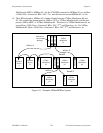
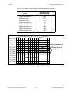
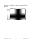
9. The next step is to determine the range of addresses, or base address, size, and direction of
the A16 window for each VXI-MXI in the system. We first assign A16 space to the VXIbus
RM Mainframe. From Figure 5-15, we see it needs 16 KB of A16 space, so we assign it the
bottom 16 KB of A16 space, addresses 0 through 3FFF hex. See Figure 5-14 for a pictorial
representation of this assignment.
10. Each first-level MXIbus link is connected to the RM through a VXI-MXI. The A16
window for MXIbus link #1 is 16 KB in size. We assign the next lowest available 16 KB
portion of A16 space to MXIbus link #1, which is address range 4000 to 7FFF hex. (See
Figure 5-14.) The base address of this window is 4000, which we enter into Figure 5-15.
The Size field for the window is i where the size of the window = 256 * 2
8-i
. 16 KB = 256 *
2
8-2
, so Size = 2. The direction of the window is in relation to the mainframe; therefore,
Direction = Out.
11. The other first-level MXIbus link is MXIbus #2, which needs 2 KB of A16 space. The next
lowest available 2 KB portion of A16 space is 8000 through 87FF hex. We set the base
address of the window to 8000. To determine the Size value, 2 KB = 256 * 2
8-5
, so Size = 5.
The direction of the window is in relation to the mainframe; therefore, Direction = Out. We
enter all of these values into the worksheet in Figure 5-15.
12. The VXI-MXI in VXIbus Mainframe #2 will be configured so that all A16 space is mapped
outward, because the mainframe does not require any A16 space. To do this, we set Base =
0, Size = 0, and Direction = Out.
13. The VXI-MXI in VXIbus Mainframe #3 should be assigned the lowest available 8 KB of
space assigned to MXIbus #1. Therefore, the base should be 4000 hex, and because 8 KB =
256 * 2
8-3
, Size = 3. The direction of the window is in relation to the mainframe; therefore,
it is In. The VXI-MXI connected to MXIbus #3 must be assigned a window within the
range of addresses assigned to Mainframe #3. Devices in Mainframe #3 need 4 KB of the
8 KB assigned to the mainframe. The other 4 KB can be assigned to MXIbus #3.
Therefore, we assign addresses 4000 to 4FFF hex to devices in Mainframe #3, and addresses


