Configuring a Two-Frame System Appendix E
VXI-MXI User Manual E-6 © National Instruments Corporation
Configuration Requirements for Two-Frame System
This section contains miscellaneous information you need to consider as you configure a
two-frame system.
BTO Unit
Notice that although the VXI-MXI in Frame A is not the VXI System Controller (not a Slot 0
device) it still has the VXI BTO unit. This VXI-MXI is, however, the MXIbus System
Controller and therefore has the MXI BTO unit as well.
Logical Addresses
Frame A contains logical addresses in the range of 0 to 7F hex. The Resource Manager must be
Logical Address 0. The VXI-MXI is Logical Address 1. Ensure that no other devices in that
frame have either of these logical addresses. In addition, no devices in Frame A should have
logical addresses of 80 hex or above (except for FF hex).
Frame B contains logical addresses from 80 hex to FE hex. The VXI-MXI in Frame B has
Logical Address 80 hex. Make sure that no other devices in Frame B have logical addresses of
80 hex or below.
Logical Address FF hex is reserved for dynamically configurable devices. You can put these
devices in either frame.
CLK10 Mapping
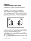
CLK 10 is routed from Frame A to Frame B over INTX in Figures E-4 and E-5. Refer to the
INTX CLK10 Mapping section of Chapter 3 if you want to change this configuration.


