Configuration and Installation Chapter 3
VXI-MXI User Manual 3-4 © National Instruments Corporation
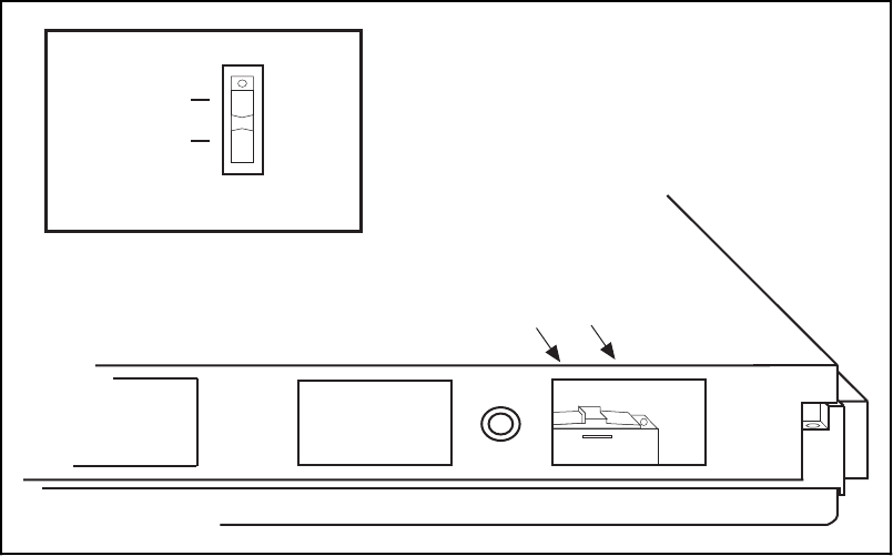
The Metal Enclosure
The VXI-MXI is housed in a metal enclosure to improve EMC performance and to provide easy
handling. Because the enclosure includes cut-outs to facilitate changes to switch and jumper
settings, it should not be necessary to remove it under normal circumstances.
Should you find it necessary to open the enclosure, remove the three screws on the top, the three
screws on the bottom, and the three screws on the right side panel of the enclosure.
VXIbus Slot 0
The VXI-MXI is shipped from the factory configured to be installed in Slot 0 of the VXIbus
mainframe. If another device is already in Slot 0, you must decide which device will be the Slot
0 device and reconfigure the other device for Non-Slot 0 use.
Warning: Do not install a device configured for Slot 0 into another slot without first
reconfiguring it for Non-Slot 0 use. Doing so could result in damage to the
Non-Slot 0 device, the VXIbus backplane, or both.
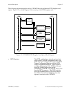
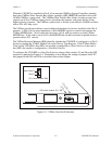
Figure 3-3 shows the default configuration settings for the VXI-MXI installed as the Slot 0
device. The position of slide switches S1 and S8 must match. For Slot 0 configuration, they
must both be in the ON position. In addition to S1 and S8, jumper block W7 and jumper blocks
W9 and W10 must be set for Slot 0 configuration. Refer to the VMEbus Timeout Chain Position
section and the CLK10 Source section later in this chapter to examine the options for these
jumper blocks.
(S8 must match S1)
S8
Non-Slot 0
Slot 0
(S1 must match S8)
S1
Slot 0
Non-Slot 0
Figure 3-3. VXIbus Slot 0 Selection


