Chapter 6 Theory of Operation
© National Instruments Corporation 6-5 VXI-MXI User Manual
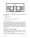
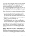
Multiple MXIbus devices can interrupt on the same interrupt line; therefore, a MXIbus interrupt
acknowledge daisy-chain is required. The MXIbus GIN and GOUT signals are normally used
for the arbitration bus grant in/bus grant out daisy-chain. However, when a MXIbus device
initiates a MXIbus IACK cycle and drives the MXIbus address modifier code hex 12, the
MXIbus GIN and GOUT lines are used as the interrupt acknowledge daisy-chain. The MXIbus
System Controller starts the interrupt acknowledge daisy-chain when it detects the address
modifier code hex 12. The interrupt acknowledge signal propagates down the daisy-chain to
each MXIbus device. If the device is not interrupting the MXIbus, it passes the signal down the
daisy-chain to the next device. If the MXIbus device is interrupting, the cycle is converted into a
VMEbus IACK cycle.
A MXIbus device not capable of generating a MXIbus IACK cycle can service an interrupt in a
remote VXIbus mainframe by reading from a designated address in the MXIbus configuration
space on the remote VXI-MXI. The external device must know which VMEbus interrupt level it
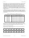
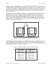
is servicing and read from the appropriate address. Table 6-1 shows the designated addresses for
VMEbus IRQ[7–1].
Table 6-1. VXI-MXI Addresses for VMEbus Interrupt Levels
VMEbus IRQ Line VXI-MXI Configuration Register to Read
VMEbus IRQ1 Interrupt Acknowledge 1 (VXI-MXI offset = 32)
VMEbus IRQ2 Interrupt Acknowledge 2 (VXI-MXI offset = 34)
VMEbus IRQ3 Interrupt Acknowledge 3 (VXI-MXI offset = 36)
VMEbus IRQ4 Interrupt Acknowledge 4 (VXI-MXI offset = 38)
VMEbus IRQ5 Interrupt Acknowledge 5 (VXI-MXI offset = 3A)
VMEbus IRQ6 Interrupt Acknowledge 6 (VXI-MXI offset = 3C)
VMEbus IRQ7 Interrupt Acknowledge 7 (VXI-MXI offset = 3E)
Reading from one of the addresses listed in Table 6-1 initiates a VMEbus IACK cycle. The
information sent back from the read is the VXIbus Status/ID information defined in the VXIbus
specification. The lower byte of the Status/ID is the logical address of the responding
interrupter. The upper byte is user defined.
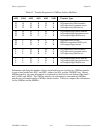
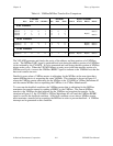
When one of the local VXI-MXI interrupt conditions is serviced by an interrupt handler, the
Status/ID information returned is as follows:
15 14 13 12 11 10 9
LINT3 LINT2 LINT1 ACFAILINT
BKOFF
TRIGINT SYSFAIL ACFAIL
8
7 65432
1
LADD7
LADD6
LADD5 LADD4 LADD3 LADD2
LADD1
LADD0
0


