Chapter 3 Configuration and Installation
© National Instruments Corporation 3-29 VXI-MXI User Manual
If your MXIbus cable has a single connector on one end and a dual-ended connector on the other
end (National Instruments part number 180760-XX or 180761-XX, where XX is the length in
meters), you can create a MXIbus system that consists of more than two devices. A MXIbus
system is defined as the set of devices physically connected by individual MXIbus cable links.
These devices form a daisy-chain in which the relative priority of a device within that chain is
determined by its proximity to the first device in the MXIbus system, the MXIbus System
Controller. Devices closer to the MXIbus System Controller have a higher priority than others in
the daisy-chain. Refer to Figure 3-20 for an example of a MXIbus system.
Begin establishing the system by connecting the end of the cable with the single connector to the
MXIbus System Controller and the end of the cable with the dual-ended connectors to the next
device in the MXIbus link. If your system contains more than two devices, connect the single
connector of the next cable to the back of the dual-ended connector that you connected to the
second MXIbus device. Connect the dual-connector end to the next device. Continue in this
manner until you have all devices in your system connected.
Note: A MXIbus system may contain no more than eight daisy-chained devices and must
have a total cable distance not exceeding 20 meters.
Secure the MXIbus cable(s) on the back of the MXIbus connector (or terminating network) using
the captive screw elements to ensure that the cable(s) will not accidentally become disconnected.
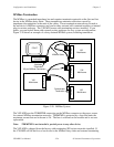
Figure 3-24 shows an AT-MXI serving as the MXIbus System Controller connected with the
single connector end of the cable, and a VXI-MXI connected with the dual-ended connector.
Figure 3-24. MXIbus Dual-Ended Cable Configuration


