© National Instruments Corporation E-1 VXI-MXI User Manual
Appendix E
Configuring a Two-Frame System
This appendix describes how to configure a system containing two mainframes linked by
VXI-MXI modules.
Configuring VXI-MXIs for a Two-Frame System
The factory configuration of the VXI-MXI is suitable for the most common system
configurations. However, a VXI system using VXI-MXI modules to extend from one mainframe
to another requires that you reconfigure the VXI-MXIs. You can find more information about
configuring a multiframe system in Chapter 3, Configuration and Installation, which describes
the switch settings, and Chapter 5, Programming Considerations, which describes the partitions
of system resources, including logical addresses. This appendix is a quick reference for systems
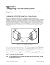
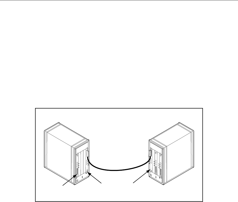
such as the one in Figure E-1, which consists of two VXI mainframes connected by a single
MXIbus link.
bus
NATIONAL
INSTRUMENTS
®
Frame A Frame B
Slot 0 Device
bus
NATIONAL
INSTRUMENTS
®
VXI-MXI,
Slot 0
VXI-MXI,
non-Slot 0
Figure E-1. A Two-Frame VXI System
The next two figures show the configuration of VXI-MXIs not equipped with the INTX daughter
card option in a two-frame VXI system. Figure E-2 shows the configuration of the VXI-MXI in
Frame A. Figure E-3 shows the configuration of the VXI-MXI in Frame B. You can find more
detailed drawings of each configurable jumper and switch in Chapter 3.
Figures E-4 and E-5 show the configuration of two VXI-MXIs equipped with the INTX daughter
card option in the same two-frame VXI system. Figure E-4 shows the VXI-MXI in Frame A and
Figure E-5 shows the VXI-MXI in Frame B.
Note: In the following figures, the switches and jumpers that you need to change from the
default settings are circled.


