


Chapter 3 Configuration and Installation
© National Instruments Corporation 3-7 VXI-MXI User Manual
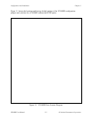
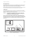
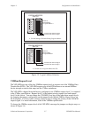
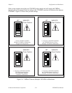
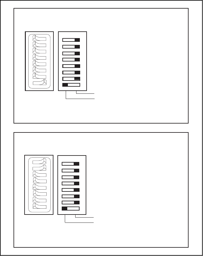
Shown at
Default setting
of Logical Address 1
LOGICAL ADDRESS
SWITCH
Push this side down for logic 0
Push this side down for logic 1
OFF ON
1
2
3
4
5
6
7
8
OFF
1 2 3 4 5 6 7 8
a. Switch Setting to Default Setting Logical Address
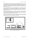
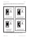
Shown at
Default setting
of Logical Address 1
LOGICAL ADDRESS
SWITCH
Push this side down for logic 0
Push this side down for logic 1
OFF ON
1
2
3
4
5
6
7
8
OFF
12345678
b. Switch Set to Logical Address hex C0
Figure 3-5. Logical Address Selection
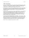
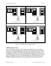
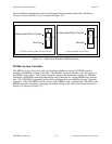
VMEbus Request Level
The VXI-MXI uses one of the four VMEbus request levels to request use of the VMEbus Data
Transfer Bus (DTB). The VXI-MXI requests use of the DTB whenever an external MXIbus
device attempts a transfer that maps into the VXIbus mainframe.
The VXI-MXI is shipped from the factory configured to use VMEbus request level 3, as required
in the VXIbus specification. Request level 3 is the highest priority request level and request
level 0 is the lowest. You can change the VXI-MXI to use any of the other three request levels
by changing the jumper configuration on the jumper blocks labeled VMEbus Request Level on
the front panel. You may want to change request levels to change the priority of the VXI-MXI
request signal. For more information, refer to the VMEbus specification.
To change the VMEbus request level of the VXI-MXI, rearrange the jumpers on the pin arrays as
shown in Figure 3-6.