


Chapter 10 x87 Floating-Point Optimizations 239
Software Optimization Guide for AMD64 Processors
25112 Rev. 3.06 September 2005
10.2 Achieving Two Floating-Point Operations per
Clock Cycle
Optimization
Pay special attention to the order and packing of the operations to sustain up to two floating-point
operations per clock cycle.
Application
This optimization applies to:
• 32-bit software
• 64-bit software
Rationale
The floating-point unit in the AMD Athlon, AMD Athlon 64, and AMD Opteron processors can
sustain up to two floating-point operations per clock cycle. However, to achieve this, you must pay
special attention to the order and packing of the operations. For example, consider multiplying a
30 × 30 double-precision matrix A by a transposed 30 × 30 double-precision matrix B, the result of
which is called C.
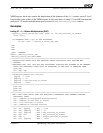
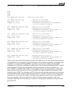
Use Efficient Addressing of FPU Data When Loading and Storing
The rows of A are 240 bytes wide, as are the columns of B. There are eight x87 floating-point
registers [ST(0)–ST(7)], and in this example, six rows of A are concurrently multiplied by a single
column of B. The address of the first element of the first row of A (A[0]) is presumed to be stored in
the EDI register, while the address of the first element of the first column of B (B[0]) is stored in ESI.
This addressing scheme might seem like a good idea, but it is not. Only 128 bytes can be addressed
forward of A[0] with 8-bit offsets, meaning the size of the instructions are only 3 bytes (2 bytes for
the instruction and 1 byte for the offset to the address stored in the general-purpose register). Upon
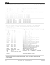
offsetting more than 128 bytes from the address in the general-purpose register, the size of the
instruction increases from 3 bytes to 6 bytes (offsets larger than 128 bytes are represented by 32 bits
rather than 8 bits). Large instruction sizes reduce the number of decoded operations to be executed
within the pipes of the floating-point unit, and as such prevent us from achieving two floating-point
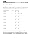
operations per clock cycle. To alleviate this, the general-purpose registers EDI and ESI are offset by
128 bytes such that they contain the addresses of A[15] and B[15]. This is beneficial because data
within 128 bytes (16 double-precision numbers) before or after these two locations can now be
accessed with instructions that are 2–3 bytes in size. The next five rows of A can be efficiently
addressed in terms of the first row. Storing the size of a single row of A (240 bytes) in the EAX