


Disassembly, Reassembly and Lubrication
CL-S6621 3-30
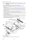
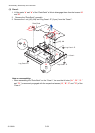
BH, M3x4 (NI)
Plate, I/F Cover
Parallel I/F Board
(Optional)
Plate Main PCB
BH, M3x4 (NI)
I/F connector
(On the "SA, Relay PCB")
Rail
(A part of the "Case L")
Connector
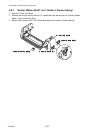
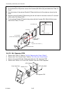
Note on installing the optional Parallel I/F Board:
1. On the back side of the printer, remove the 2 screws (BH, M3x4 (NI)) and detach the “Plate, I/F
Cover”.
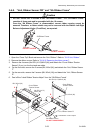
2. Align the bottom of the optional Parallel I/F Board with the rail of the printer as shown by the
arrow.
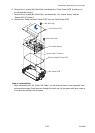
3. Slide the optional Parallel I/F Board along the rail and insert its connector into the I/F connector
(J201) of the “SA, Relay PCB”).
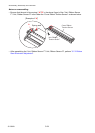
4. Fix the optional Parallel I/F Board to the printer with the 2 screws (BH, M3x4 (NI)) that were
used for the “Plate, I/F Cover”.
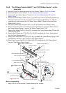
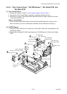
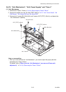
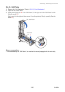
3-6-12. SA, Opepane PCB
1. Remove the “Case U”. Refer to “3-6-3(1) Removing the “Case U” Block”.
2. Remove the “Unit, Control Panel”. Refer to “
3-6-11(1) Unit, Control Panel”.
3. Remove 3 screws (PHT (#2), M3x6) and detach the “SA, Opepane PCB”.
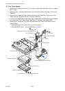
4. Remove the “Switch, CL-S” and “LED, Window” from the “Cover Ope-pane”.
SA, Opepane PCB
LED, Window
Switch, CL-S
Cover Ope-Pane
PHT (#2), M3x6