Operation of Control Parts
2-27 CL-S6621
J5
SA, Head
+3.3V
5
R53
HDTMP
U1A
CPU
ANI2
7
Head Temp.
Thermistor
C82
R54
U16B
BA2903SFV
-
+
5
6
7
+3.3V
R39
+3.3V
R40
C41
R41
R42
HDTMP
C11
C6
B2_28
B2_27
U14
FPGA
nTEMP_ERROR
nTEMP_ENABLE
HDTMP
Error: Low
8
[SA, Main PCB]
TEMP ERROR Detection
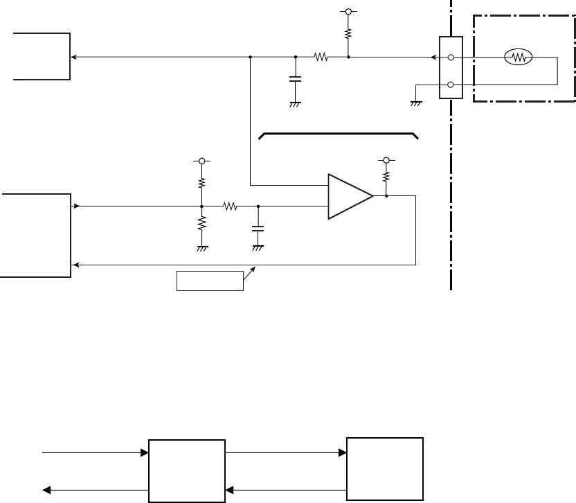
(4) Head temperature sensor
The head temperature sensor is used to detect the temperature of the “SA, Head”. This sensor
is a thermistor incorporated in the “SA, Head”. Since the resistance of the thermistor changes
according to a temperature change, the voltage at pin 7 (HDTMP) of U1A (CPU) changes
accordingly. The CPU senses the voltage at pin 7 (HDTMP) to detect the head temperature.
According to the temperature of the “SA, Head”, the CPU controls the printing pulse width
applied to the thermal elements to keep the printing density constant.
Printing operation when the head temperature rises:
If the head temperature reaches 70°C (158°F), printing stops after printing the current label. In
this case, the PRINT LED and CONDITION LED simultaneously blink on the operation panel.
When the temperature of the “SA, Head” falls below 60°C (140°F), the LEDs stop blinking and
printing will be resumed.
For further safety, an abnormally high temperature detection circuit is provided. In case this
circuit is activated, the System error is displayed, and the printer stops.
The comparator U16B detects if the level at pin 5 (HDTMP) (i.e., the temperature of the “SA,
Head”) exceeds a certain reference level determined by the output from pin C11
(nTEMP_ENABLE) of U14 (FPGA) (i.e., the predetermined allowable limit temperature). If it
does, nTEMP_ERROR at pin C6 goes “Low” level and this signal is fed to U14 (FPGA). Then,
the System error is displayed and the printer stops. At this time, nTEMP_ENABLE at pin C11 is
set to “Low” level so that nTEMP_ERROR is securely maintained at “Low” level. (To clear the
System error, you need to turn OFF the printer once and then turn it ON.)
60°C
(140°F)
70°C
(158°F)
Printing
(Stops)
(Stop)
Printing
Printing


