


Operation of Each Mechanism
CL-S6621 2-16
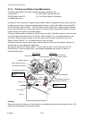
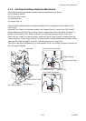
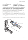
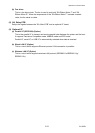
2-1-8. Media Offset Adjustment Mechanism
The major components of the media thickness adjustment mechanism are:
(a) Cam Head Adjust (c) Spring Head Holder
(b) SA Head Adjust Lever (d) Plate Holder Head
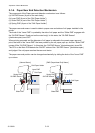
According to the softness of media, the thermal element position is displaced from the optimum
position. The head offset adjustment mechanism is used to correct this by moving the “SA Head”
back and forth a little. By performing the head adjustment properly, optimum printing quality is
obtained. (When shipping, the Media thickness adjustment dial is set to “1” for soft media.)
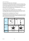
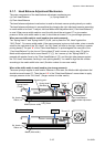
When soft media is used (thin thermal paper, label paper, etc.):
When soft media is used, the optimum position of the thermal elements will be nearly right above
the center of the “SA2_ Platen”. (In dial No. “1”, they are aligned with the platen center.)
When hard media is used (tag paper):
When hard media is used, the optimum position of the thermal elements will shift toward the front a
little from the center of the “SA2_Platen”, i.e. toward the left viewing from the right side of the
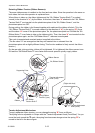
“SA2_ Platen” as shown below. As the optimum position varies according to the hardness of media,
it is necessary to adjust the Media thickness adjustment dial from “1” to up to “9” for optimum
printing. As the dial is turned (), the “SA Head Adjust Lever” swings up and down () as its
projection “A” moves along the groove of the dial.
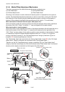
The “Plate Holder Head” end is pinched by the “Spring Head Holder” at end “B” of the “SA, Head
Adjust Lever”. (Namely, both parts are connected via the “Spring Head Holder”.)
Therefore, as the “SA, Head Adjust Lever” swings up and down (), the “Plate Holder Head”
swings up and down accordingly (). With this movement of the “Plate Holder Head”, the thermal
element position slightly moves back and forth against the “SA2_Platen”.
0
0
0
9
9
9
For soft media
For hard media
Ribbon
SA2_Platen
Media
SA, Head
(Media Thickness Adjustment Dial)
Plate Holder Head
SA Cover Frame (Fixed)
Supporting
point
Supporting
point
Groove
B
[Right side view]
B
Spring Head Holder
Cam Head Adjust
A
B
SA Head Adjust Lever
[Section "B" upside-down view]