


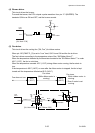
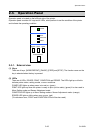

Operation of Control Parts
2-39 CL-S6621
To/From
U14
FPGA
23
22
21
nSLCT-IN/CTS, nATFD-XT/DSR
nSTROBE/OCIO, nINIT/nPRIME
BUSY/RTS, nACKNLG/DTR
nFAULT, SLCT/PPON0
PE, DSWOUT, TXD0/SO0/OBDIR
IFRESET
RXD0/SI0, SCK0
VBUS
I/F PCB
(Option)
DATA0-DATA7
+24V
+5V
To/From
U1A CPU
J17
28-32
20
4-11
1-3
12-18
24,27
25,26
[SA, Main PCB]
USB_D+
USB_D-
33-38,40
R125
R127
Q29
DTA114EM
C133
R126
UBINTP
4
6
5
9
8
10
1
3
2
+3.3V
+3.3V
U1A
CPU
USBON
P76
172
D23
121
UDP
UDM
USB connection detecting circuit
R128
U27C
U27A
U27B
UDP
UDM
160
161
High when USB
connector is connected.
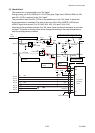
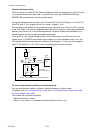
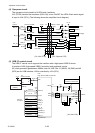
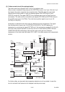
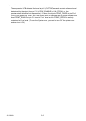
(6) RS232C I/F circuit
The RS232C I/F circuit consists of U25 and U26 (receiver/transmitter) and receives and
transmits the RS232C I/F signals.
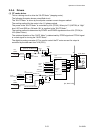
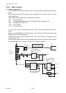
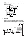
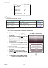
(7) Option I/F circuit
The optional I/F circuit consists of an ordinary USB interface circuit and communication I/F
signal lines that are connected to U1A (CPU) and U14 (FPGA).
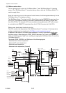
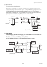
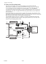
NAND gates (U27A, U27B and U27C) and transistor Q29 consist of a USB connection
detecting circuit. When USB I/F is connected to the printer, pin 23 (VBUS) of J17 is set to
“High”. The detection circuit detects this level and outputs a UBINTP pulse to the CPU to
inform of the USB connection.
13
15
12
10
Vcc
T1IN
T2IN
R1OUT
R2OUT
U25
Receiver/Transmitter
2
20
3
6
J16
8
17
16
9
TXD1
DTR1
RXD1
DSR1
19
+3.3V
[SA, Main PCB]
ICL3222EIVZ
20
nGRESET
SHDN
To/From
U1A
CPU
4
5
25
T1OUT
T2OUT
R1IN
R2IN
13
15
12
10
Vcc
T1IN
T2IN
R1OUT
R2OUT
U26
8
17
16
9
RTS1
CTS1
RS_INIT
19
+3.3V
ICL3222EIVZ
20
nGRESET
SHDN
T1OUT
T2OUT
R1IN
R2IN
TXD
DTR
RXD
DSR
RTS
CTS
INIT
RS232C I/F
Receiver/Transmitter