


CL-S6621 3-2
CHAPTER 3 DISASSEMBLY AND MAINTENANCE
TABLE OF CONTENTS
3-1. Maintenance Precautions ...............................................................................................3-4
3-2. Cleaning..........................................................................................................................3-5
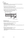
3-3. Lubrication ......................................................................................................................3-5
3-3-1. Lubrication frequency.........................................................................................3-5
3-3-2. Types of lubricant ...............................................................................................3-5
3-3-3. Quantity of lubricant ...........................................................................................3-5
3-3-4. Adhesive ............................................................................................................3-5
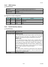
3-4. Maintenance Tools List ...................................................................................................3-6
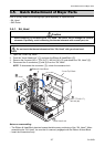
3-5. Quick Detachment of Major Parts...................................................................................3-7
3-5-1. SA, Head............................................................................................................3-7
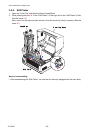
3-5-2. SA2 Platen .........................................................................................................3-8
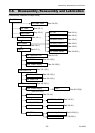
3-6. Disassembly, Reassembly and Lubrication .................................................................... 3-9
3-6-1. “Cover Top” and “Support Top Cover” ................................................................ 3-10
(1) Removing the “Cover Top” Block............................................................... 3-10
(2) Removing the “Cover Top” and “Support Top Cover” ................................3-11
3-6-2. Unit, Ribbon .......................................................................................................3-12
3-6-3. Case U ...............................................................................................................3-14
(1) Removing the “Case U” Block ................................................................... 3-14
(2) Removing the “Case U”............................................................................. 3-17
3-6-4. SA, Fan ..............................................................................................................3-18
(1) Removing the ribbon covers......................................................................3-18
(2) Removing the “SA, Fan”............................................................................ 3-18
3-6-5. Ribbon Gears.....................................................................................................3-19
3-6-6. “SA Ribbon Motor F/R” and “SA, Ribbon PCB”.................................................. 3-21
3-6-7. “Holder, Ribbon Shaft” and “Holder 2 Tension Spring” ....................................... 3-22
3-6-8. “Unit, Ribbon Sensor F/R” and “SA Ribbon Frame” ........................................... 3-23
3-6-9. “SA, Ribbon Tension Shaft F” and “SA, Ribbon Sensor” on the front side......... 3-25
3-6-10. “SA, Ribbon Tension Shaft R” and “SA, Tension Sensor” on the rear side ........3-26
3-6-11. “Unit, Control Panel”, “SA PNE Sensor”, “SA, Relay PCB” and
“SA, Main PCB” .............................................................................................................3-
27
(1) Unit, Control Panel ....................................................................................3-27
(2) SA PNE Sensor .........................................................................................3-27
(3) “SA, Relay PCB” and “SA, Main PCB” ...................................................... 3-28
3-6-12. SA, Opepane PCB .............................................................................................3-30
3-6-13. “Unit, Mechanism”, “Unit, Power Supply” and “Case L” .....................................3-31
(1) Unit, Mechanism........................................................................................3-31
(2) Unit, Power Supply....................................................................................3-32
(3) Case L .......................................................................................................3-34
3-6-14. SA2 Platen .........................................................................................................3-35
3-6-15. Unit, Sensor U....................................................................................................3-36
3-6-16. “SA TRA Sen PCB” and “Gear Bevel Lead Screw U”......................................... 3-38
3-6-17. Unit, Head ..........................................................................................................3-41