


Operation of Each Mechanism
2-17 CL-S6621
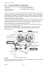
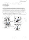
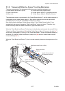
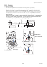
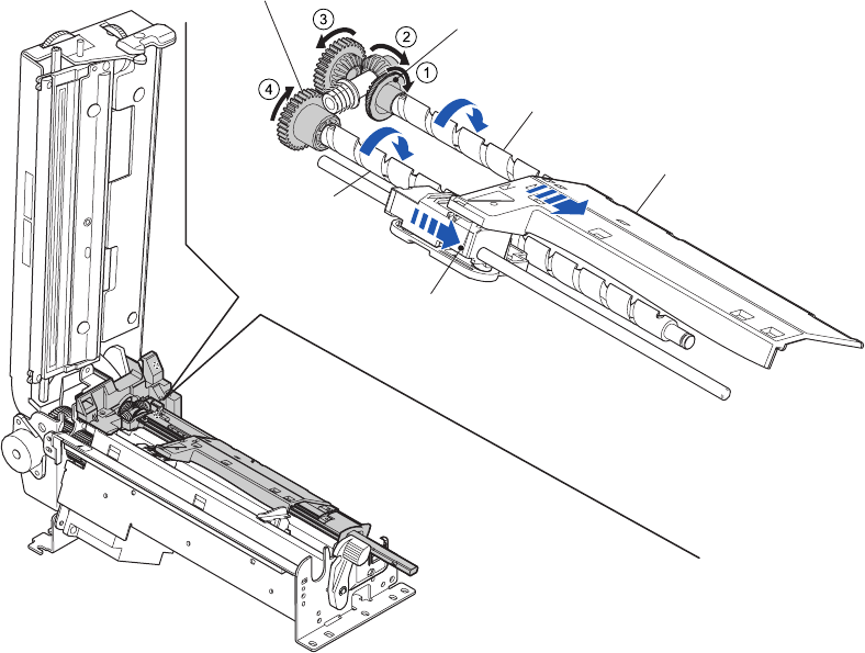
2-1-9. Transparent/Reflective Sensor Travelling Mechanism
The major components of the transparent/reflective sensor travelling mechanism are:
(a) Gear Bevel Lead Screw U (Blue) (d) Shaft Lead Screw (Upper/Lower)
(b) Gear Lead Screw L (e) Holder Sensor Adjust U (Transparent sensor)
(c) Gear train (f) Holder Sensor Adjust L (Reflective Sensor)
The transparent sensor is incorporated in the “Holder Sensor Adjust U” and the reflective sensor is
incorporated in the “Holder Sensor Adjust L”. Both sensor housings move to the right and left
simultaneously by turning the “Gear Bevel Lead Screw U” (blue).
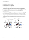
Note that the sensor housings (“Holder Sensor Adjust U” and “Holder Sensor Adjust L”) are
engaged with the groove of respective “Shaft Lead Screw” (upper and lower). Therefore, they
move horizontally when the “Shaft Lead Screw” (upper and lower) turns.
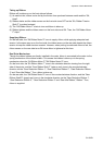
When the “Gear Bevel Lead Screw U” (blue) turns in the direction as shown by the arrow (), the
“Screw Lead Screw” (upper) turns (“a”) and the “Holder Sensor Adjust U” moves to the right (“a’ ”).
At this time, via the gears (() and ()), the “Gear Lead Screw L” turns in the direction shown by
the arrow (), and the “Screw Lead Screw” (lower) turns (“b”) and the “Holder Sensor Adjust L”
moves to the right (“b’ “).
When the “Gear Bevel Lead Screw U” (blue) is turned reversely, the sensor housings move to the
left.
Shaft Lead Screw
(Upper)
Shaft Lead Screw
(Lower)
a
a’
b
b’
Holder Sensor Adjust U
(Transparent Sensor)
Holder Sensor Adjust L
(Reflective Sensor)
Gear Bevel Lead Screw U (Blue)
Gear Lead Screw L