


Disassembly, Reassembly and Lubrication
CL-S6621 3-40
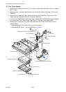
Notes on reassembling:
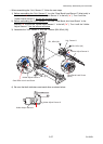
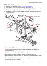
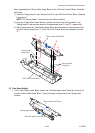
• Apply FLOIL G-311S to the groove of the “Shaft Lead Screw” shown by the
mark.
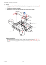
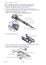
• When assembling the “Spring Guide Paper U”,
follow the next steps.
1) First, hook the end “B” as shown below.
2) Next, insert the end “A” into the opening “a”
and move it from “a” to “a’ “ to hook it on
the opening “a’ “ as shown below.
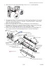
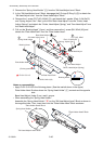
• When assembling the “FFC, TRA Sensor”, run it as shown below.
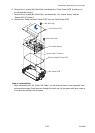
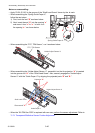
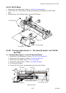
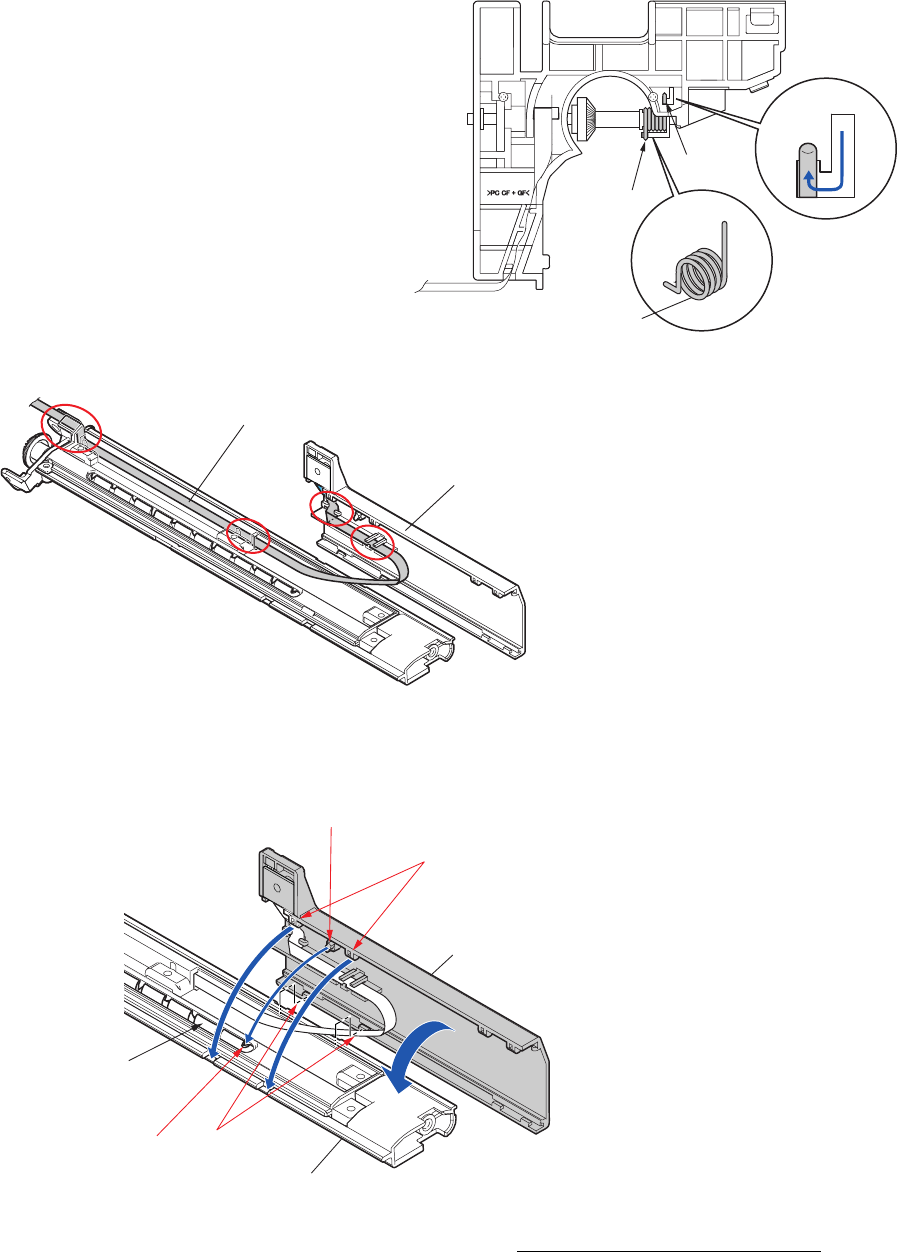
• When assembling the “Holder Adjust Sensor U”, assemble it so that its projection “A” is inserted
into the groove end “A’ ”of the “Shaft Lead Screw”. Also, securely engage the “Holder Adjust
Sensor U” with the “Guide Paper U” by aligning the projected parts “B” and “B’ ”.
• When the “SA TRA Sen PCB” is replaced with new one, perform the sensor adjustment.
Refer to
“
3-7-1 Transparent/Reflective Sensor Position Adjustment.
Holder Adjust Sensor U
FFC, TRA Sensor
A
a
a’
B
B
A
Spring Guide Paper U
Groove end "A’ "
B’
Shaft Lead Screw
Projection "
A
"
B
Holder Adjust Sensor U
Guide Paper U