Disassembly, Reassembly and Lubrication
CL-S6621 3-38
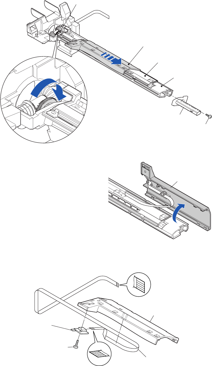
3-6-16. “SA TRA Sen PCB” and “Gear Bevel Lead Screw U”
1. Remove the “Unit, Mechanism”. Refer to “3-6-13(1) Unit, Mechanism”.
2. Remove the “Unit, Sensor U”. Refer to “
3-6-15 Unit, Sensor U”.
3. Remove the 1 screw (BHT (#2), M3x6 (NI)) and detach the “Knob Guide Paper U”.
4. Turn the “Gear Bevel Lead Screw U” (blue knob) in the direction as shown in the magnified
view to move the “Head Adjust Sensor U” to the right.
NOTE: Turn the “Gear Bevel Lead Screw U” (blue knob) until it stops.
5. Open the “Head Adjust Sensor U”.
6. Remove the 1 screw (No.0, TFH (PT4-0.5), M2x4) from the “SA TRA Sen PCB”, and then
disconnect the “FFC TRA Sensor” from the “SA TRA Sen PCB”.
7. Remove the “FFC TRA Sensor” from the “Holder Adjust Sensor U”.
Holder Adjust Sensor U
Knob Guide Paper U
Guide Paper U
Cover Guide Paper U
Holder Adjust Sensor U
Gear Bevel Lead Screw U (Blue Knob)
BHT (#2), M3x6 (NI)
J9
Holder Adjust Sensor U
No.0, TFH (PT4-0.5), M2x4
SA TRA Sen PCB
FFC, TRA Sensor


