


CL-S6621 2-2
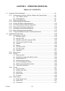
CHAPTER 2 OPERATING PRINCIPLES
TABLE OF CONTENTS
2-1. Operation of Each Mechanism .......................................................................................2-4
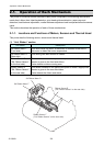
2-1-1. Locations and Functions of Motors, Sensors and Thermal Head ......................2-4
(1) “Unit, Ribbon” section................................................................................2-4
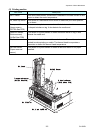
(2) Printing section.......................................................................................... 2-5
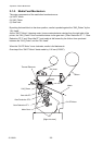
2-1-2. Media Feed Mechanism.....................................................................................2-6
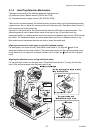
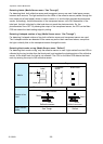
2-1-3. Label/Tag Detection Mechanism ........................................................................2-7
2-1-4. Printing and Ribbon Feed Mechanism ...............................................................2-10
2-1-5. Print Head Up/Down Detection Mechanism.......................................................2-13
2-1-6. Paper Near End Detection Mechanism..............................................................2-14
2-1-7. Head Balance Adjustment Mechanism ..............................................................2-15
2-1-8. Media Offset Adjustment Mechanism.................................................................2-16
2-1-9. Transparent/Reflective Sensor Travelling Mechanism .......................................2-17
2-2. Operation of Control Parts.............................................................................................. 2-18
2-2-1. Configuration of Printer ......................................................................................2-18
(1) AC power supply .......................................................................................2-19
(2) SA, Main PCB............................................................................................2-19
(3) Operation panel (SA, Opepane PCB)........................................................2-20
(4) Thermal print head (SA, Head).................................................................. 2-20
(5) Sensors .....................................................................................................2-20
(6) Motors........................................................................................................2-20
(7) SA, Ribbon PCB........................................................................................2-20
(8) SA, Relay PCB ..........................................................................................2-21
(9) Optional I/F................................................................................................2-21
2-2-2. Memory map ......................................................................................................2-22
2-2-3. Sensors..............................................................................................................2-23
(1) Head up switch..........................................................................................2-23
(2) Transparent sensor and reflective sensor ................................................. 2-24
(3) Ribbon Sensor F/R....................................................................................2-26
(4) Head temperature sensor.......................................................................... 2-27
(5) PF motor temperature sensor.................................................................... 2-28
(6) Ribbon motor temperature sensor.............................................................2-29
(7) Paper Near End sensor.............................................................................2-30
2-2-4. Drivers................................................................................................................2-31
(1) PF motor driver..........................................................................................2-31
(2) Ribbon motor driver...................................................................................2-32
(3) Head driver................................................................................................2-33
(4) Buzzer driver .............................................................................................2-35
(5) Fan driver ..................................................................................................2-35
2-2-5. Other circuits ......................................................................................................2-36
(1) Power supply circuit...................................................................................2-36
(2) Reset circuit............................................................................................... 2-37
(3) Clock circuit ............................................................................................... 2-37