


Operation of Control Parts
CL-S6621 2-34
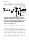
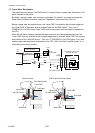
Thermal resistance check:
When the printer is turned ON, the thermal resistance check is conducted. If any fault is found,
it is memorized and, when the printer is turned ON next time, the CONDITION LED and
ERROR LED alternately blink on the operation panel.
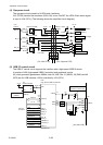
During the thermal resistance check, pin P15 (nHCVON) of U14 (FPGA) goes "Low" level, Q1
turns ON, and +3.3V is supplied to the “SA, Head”, instead of +24V.
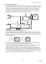
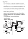
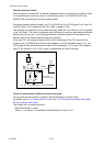
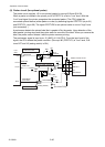
The following is a simplified circuitry under checking, where Q1 turns ON and +3.3V is applied
to the “SA, Head”. The thermal resistance check (dot check) is done by selecting each thermal
element (dot) one by one. In the following example, a thermal element with resistance R1 is
selected (rest of the thermal elements are disconnected).
At the point "A", the voltage divided by R45 and R1 is developed. The CPU monitors this
voltage at pin 10 (HDRES) and checks if the voltage is out of the allowable range. If it is, the
CPU judges that the thermal element is defective. (For example, if R1 is open, the voltage at
point “A” will be about +3.3V. If R1 is open, corresponding dot will be missing.)
To see the total number of defective thermal elements:
You can print the total number of defective thermal elements in Service mode.
For details, refer to “(3) Factory/Service mode” and “(3-3) Factory/Service Mode menu table -
(b) Service Mode menu table”.
The number will be printed as follows.
Bad head element: n dot(s)
Where, n is a number. If no defective thermal element is found, n is 0.
+3.3V
U1A
CPU
R45
R1
A
R1, R2, ... ,Rn: Resistance of thermal elements
Q1
SA, Head
(Thermal Head)
R46
HDRES
ANI5
10
+3.3V
R2
ON
OFF